# Rhinoceros - Modeling Tools for Designers > Design, Model, Present, Analyze, Realize... -------------------------------------------------------------------------------- # Video player Source: https://www.rhino3d.com/en/video/ Video player -------------------------------------------------------------------------------- # Bankcard Verification Code Source: https://www.rhino3d.com/en/vcode/ This page tells you how to find the verification code on the back of your card. Your verification code is located on the back of your card. It is a three-digit, non-embossed number printed on the signature panel. If there are more than three digits in the number, the card verification code is the **rightmost three digits**. ![Bankcard verification code](https://www.rhino3d.com/en/vcode/cv.gif) -------------------------------------------------------------------------------- # Grasshopper Player Source: https://www.rhino3d.com/en/features/grasshopper/player/ Turn your Grasshopper definitions into Rhino commands. This feature brings a new set of Grasshopper components that bring inputs/outputs from Grasshopper to the Rhino Command Line. Grab inputs, define types and outputs for your command to run or print to the command prompt: ![Grasshopper Player components](https://www.rhino3d.com/en/features/grasshopper/player/ghp-components4.png) With only this handful of additional components, you can wrap your definitions as Rhino commands that create building components, such as walls... ...or even complex parametric assemblies such as curving masonry... ## Try It * * Download the [ Lamp.3dm](Lamp.3dm) model and the [ Lamp.gh](Lamp.gh) definition. * Open *Lamp.3dm*, run the `GrasshopperPlayer` command, enter the path to the downloaded, _Lamp.gh_, and follow the command prompts. * Try out a couple more examples: [ Wall.gh](Wall.gh) and [ BrickWall.gh](BrickWall.gh). * [Ask questions and give feedback](https://discourse.mcneel.com/c/grasshopper/2). -------------------------------------------------------------------------------- # PBR Materials Source: https://www.rhino3d.com/en/features/rendering/materials-and-textures/pbr/ For rendering professionals who wants realistic looking materials when rendering inside Rhino, Physically Based Rendering materials are beautiful and easy to use. That’s not all that makes PBR materials superior; they are also easier to design. You can create a material yourself or download a PBR material from [Poly Haven](https://polyhaven.com/) or [ambientCG](https://ambientcg.com/) and load it into Rhino directly from the zip file. ## Before and After PBR materials correspond much better with a physical material's characteristics than the old custom materials found in previous versions of Rhino… ## Try It * * Navigate to the _Material Editor_. * Click the sign and, from the list, choose to add a _Physically Based Material_ ![PBR Material icon 1](https://www.rhino3d.com/images/pbr_material_24.png) or _Create Physically Based Material from texture files_... ![PBR Material icon 2](https://www.rhino3d.com/images/create_physically_based_material_from_texture_files_24.png) * Ask questions and give feedback on the [Discourse Forum](https://discourse.mcneel.com). -------------------------------------------------------------------------------- # Trademarks & Usage Source: https://www.rhino3d.com/en/mcneel/trademarks/ This page lists the trademarks of TLM, Inc., doing business as Robert McNeel & Associates®. ## Trademarks The following are registered trademarks of TLM, Inc., doing business as Robert McNeel & Associates®. * Rhinoceros® * Rhino® * Rhino3D® * Flamingo® * Bongo® * Grasshopper® * openNURBS® * RhinoInside® * Rhino Inside® * RhinoCompute® * Robert McNeel & Associates® The following are trademarks of TLM, Inc., doing business as Robert McNeel & Associates®. * Rhino for Mac™ * Rhinomac™ * iRhino 3D™ * The Zoo™ * CloudZoo™ **NOT:** * Rhinoceros 1.1 or Rhinoceros v. 1.1 or Rhinoceros ver. 1.1 * Rhinoceros 2 or Rhinoceros v. 2 or Rhinoceros ver. 2.0 * Rhinoceros 3 or Rhinoceros v. 3 or Rhinoceros ver. 3.0 * Rhinoceros 4 or Rhinoceros v. 4 or Rhinoceros ver. 4.0 * Rhinoceros 5.0 or Rhino 5.0 * Rhinoceros 6.0 or Rhino 6.0 * Rhinoceros 7.0 or Rhino 7.0 * Rhinoceros 8.0 or Rhino 8.0 * RhinoCAD * Rhino 3D, Rhinoceros 3D, or Rhino3D * MacRhino, Rhino for OS X, or Rhino OS X ### Usage The current product name is **Rhinoceros**, **Rhino**, **Rhinoceros 8**, or **Rhino 8**. Use "Rhinoceros®" or "Rhino®" the first time you use the name in text. After that, the name can be shortened to "Rhino." The ® special character only needs to appear once in the document. The ® can be replaced by saying, "Rhinoceros is a registered trademark of Robert McNeel & Associates." When the Rhino graphic is displayed on a webpage, use our [Design System & Graphics](/reseller/graphics). They can also be used on print materials. In a graphic, Rhinoceros, in Arial Bold type, should be printed on black with the "Rhino" in white and "ceros" in red. When the Rhino graphic is printed on a white background, "Rhino" is black and "ceros" is red (Pantone `185c` or RGB `255,0,0`). When the Rhino graphic is monochrome on a black background, "Rhino" is white and "ceros" is 50% gray. When the Rhino graphic is monochrome on a white background, "Rhino" is black and "ceros" is 50% gray. ### #hashtags Please use these: * `#rhino3d` * `#grasshopper3d` ### Microsoft Intellectual Property Details on using Microsoft intellectual property can be found [here](https://www.microsoft.com/en-us/legal/intellectualproperty). ### Apple Intellectual Property Details on using Apple intellectual property can be found [here](https://www.apple.com/legal/intellectual-property/). [Reseller Ordering, Prices & Discounts](/reseller) | [Design System & Graphics](/reseller/graphics) -------------------------------------------------------------------------------- # Repair Rhino's Installation Source: https://www.rhino3d.com/en/docs/guides/deployment/repair-rhino-installation/ Run this utility to repair Rhino and its dependencies when Rhino for Windows can't install, uninstall, upgrade, or repair. ## Symptom Rhino for Windows fails to install, uninstall, or repair with error code -2147023284 ### Affected Versions of Rhino * Rhino 9 for Windows * Rhino 8 for Windows * Rhino 7 for Windows ## Resolution 1. Download [RhinoInstallRepair.exe](https://files.mcneel.com/rhino/8/RhinoInstallRepair.exe) 1. Run RhinoInstallRepair.exe\ The utility will: * Prompt to run with Administrator permissions * Detect the versions of Rhino that are currently installed * Download the installers for the broken installations * Repair the installations * Repair any required versions of the Microsoft C-Runtime and .NET -------------------------------------------------------------------------------- # Denoisers Source: https://www.rhino3d.com/en/features/rendering/denoisers/ Produce beautiful renderings in a fraction of the time using Denoiser Post Effect filters. Denoisers use AI to remove the grainy "noise" from your draft renderings, dramatically reducing the time to reach a high-quality image. This image took about 10 seconds to render on modern hardware: ## Try It 1. 1. Run the `PackageManager` command. 1. Search for the denoiser you want to install. Available denoisers are: * *Intel denoiser* (Works on most systems, recommended for Rhino for Mac) * *NVIDIA denoiser* (For Windows computers with modern NVIDIA GPUs) * *AMD denoiser* (For systems with modern AMD GPUs) 1. Select a denoiser and click *Download and Install*. 1. When the installation finishes, restart Rhino. 1. Render your image and in the *Post Effects tab*, add and check the *Denoiser* checkbox once the rendering has finished. 1. Ask questions and give feedback on the [Discourse Forum](https://discourse.mcneel.com). -------------------------------------------------------------------------------- # LayerBook Source: https://www.rhino3d.com/en/features/layerbook/ Use LayerBook to create slideshow style presentations in your models using Rhino directly. ## Try It - - Download and open the [ LayerBook-Demo.3dm](LayerBook-Demo.3dm) model. - Run the `LayerBook` command. - In the command-options, click the *Next* or *Previous* options or type `1` and press *enter* to rewind to the first layer. - To learn to use `LayerBook` in depth, download and open the [ LayerBook-Instructions.3dm](LayerBook-Instructions.3dm) model and follow along. - Ask questions and give feedback on the [Discourse Forum](https://discourse.mcneel.com). -------------------------------------------------------------------------------- # QuadRemesh Source: https://www.rhino3d.com/en/features/quadremesh/ QuadRemesh lets you create a quad-dominant mesh from mesh and NURBS geometry. ## Try It * * Download and open the [ QuadRemeshScrolls.3dm](QuadRemeshScrolls.3dm) model. * Run the **`QuadRemesh`** command, or click the QuadRemesh button on the SubD toolbar. * [Read the Help Documentation for QuadRemesh](https://docs.mcneel.com/rhino/8/help/en-us/commands/quadremesh.htm). * [Ask questions and give feedback](https://discourse.mcneel.com/). * Grasshopper users can use the new QuadRemesh components. * Developers: `Rhino.Geometry.Mesh.QuadRemesh()` is available in RhinoCommon for use in C# and Python. ## Examples Horse mesh after retopology Find the principal curvature with the help of the guide curve feature (highlighted in red) Multiple resolutions for optimized SubD conversion, UV Mapping, 3D Printing, etc. Symmetry for organized topology. Hard edge detection to preserve sharp corners Remesh to SubD to soften hard to fillet areas for rendering. ## Before and After ## See Also * [Is Your Mesh Really Good to Go?](/for/medical-and-dental/quadremesh/) - QuadRemesh for the medical and dental industry -------------------------------------------------------------------------------- # Clash Detection Source: https://www.rhino3d.com/en/features/grasshopper/clash-detection/ Quickly search a large number of objects to find points of intersection between pairs of clashing objects. ## BIM Clashes Take advantage of the Clash component along with any other Grasshopper plugin, including [Rhino.Inside.Revit](/features/rhino-inside-revit), to see where elements overlap: ![Clash with Rhino.Inside.Revit](https://www.rhino3d.com/en/features/grasshopper/clash-detection/clash-rir.png) ## Try It * * Download and open the [ Clash.gh](Clash.gh) definition in Grasshopper. * Developers: `Rhino.Geometry.Intersect.MeshClash()` is available in RhinoCommon for use in C# and Python. [Details...](https://github.com/mcneel/rhino-developer-samples/blob/7/rhinocommon/cs/SampleCsCommands/SampleCsClashMeshes.cs) * Ask questions and give feedback on the [Discourse Forum](https://discourse.mcneel.com). * Are you just looking to find clashes within your Rhino model? There's no need to run it from Grasshopper; you can also run the `Clash` command within Rhino itself... -------------------------------------------------------------------------------- # Grasshopper Component Placeholders Source: https://www.rhino3d.com/en/features/grasshopper/placeholders/ Placeholder component for missing plugins. This is often useful when updating older definitions. Once the definition is open, you can find and replace them with the correct components. ## Find The Missing Pieces Placeholders are just temporary. Now, to get that definition working, visit: * [Food4Rhino](https://www.food4rhino.com): Apps for Rhino and Grasshopper. * [Package Manager](/features/package-manager): -------------------------------------------------------------------------------- # 90-Day Evaluation Source: https://www.rhino3d.com/en/docs/guides/licensing/90-day-evaluation/ Try the full version of the latest Rhino free for 90 days, and see what happens to your work when the evaluation ends. ## 90-Day Eval Terms *One evaluation per customer, per major version* 1. Remember that it is a **90-day evaluation** of the latest **Rhino (full version)**. 1. After 90 days, **saving and plug-ins stop working**, unless you buy a license key. 1. We absolutely **do not offer an extension** of the 90-day evaluation for any reason. 1. The 90-day Evaluation license is **not upgradable**, meaning if you want to continue using Rhino, you must purchase the full Educational (discounted) or Commercial license, not an upgrade. ## 90-day Eval Setup Summary Follow these steps to create your account and install your **Rhino 90-Day Evaluation** correctly.
▶️ https://www.rhino3d.education/courses/license-support/lectures/53044383 1. Create your Rhino account 1. Check your email 1. Accept McNeel's conditions 1. Copy your license key and select your language 1. Install the **90-Day Rhino Evaluation** ## 90-day Eval Setup Process *How to create your Rhino account and install your evaluation license* 1. Visit [**www.Rhino3D.com**](https://www.rhino3d.com), where you can download the **90-Day Rhino Evaluation**. 2. Select -> **Download** ![Rhino3d.com homepage](https://www.rhino3d.com/en/docs/guides/licensing/90-day-evaluation/90-day-eval-01.png) 3. Select which **Rhino** license you want to download for **Windows** or **Mac**. ![Rhino3d.com download](https://www.rhino3d.com/en/docs/guides/licensing/90-day-evaluation/90-day-eval-02.png) 4. Select: “**Login or Create a Rhino Account to Download**” and this link will take you to this page: [**accounts.rhino3d.com**](https://www.rhino3d.com/my-account/) ![Rhino3d.com login](https://www.rhino3d.com/en/docs/guides/licensing/90-day-evaluation/90-day-eval-03.png) 5. Select “**Create a new account**,” which will take you to a page where you will enter your email and personal information. ![Rhino3d.com create account](https://www.rhino3d.com/en/docs/guides/licensing/90-day-evaluation/90-day-eval-04.png) 6. Enter your name, email, and personal information. Note that you can continue with your **Google** account if you want! ![Rhino3d.com personal info](https://www.rhino3d.com/en/docs/guides/licensing/90-day-evaluation/90-day-eval-05.png) 7. After you confirm your details and select **Create a new account**, you will receive an email from **tech@mcneel.com.** You must confirm the creation of your account, and you will have a few minutes to do so. If you do not see it in your inbox, look for it in your junk emails. ![Check email](https://www.rhino3d.com/en/docs/guides/licensing/90-day-evaluation/90-day-eval-06.png) 8. This page will appear in your browser shortly. After a few seconds, you will be able to **download** your license along with the **key**. It is important to copy and save the key securely. ![Login link success](https://www.rhino3d.com/en/docs/guides/licensing/90-day-evaluation/90-day-eval-07.png) 9. To receive your **Rhino license key**, you will need to agree to McNeel's privacy policy. ![Agree to privacy policy](https://www.rhino3d.com/en/docs/guides/licensing/90-day-evaluation/90-day-eval-08.png) 10. You can now download your 90-day **evaluation license** in your preferred language. The **key** from your **Rhino license** must be copied. ![Download Rhino](https://www.rhino3d.com/en/docs/guides/licensing/90-day-evaluation/90-day-eval-09.png) 11. You can now download a 90-day evaluation of Rhino and install it on your computer. *Enjoy your evaluation period.* You can learn more about managing your **account** by watching these short, step-by-step videos. ## Frequently Asked Questions (FAQ) This section covers how to create your **Rhino account**, how to validate your 90-day evaluation license, and additional information that will be very helpful to you in managing your Rhino account. - [▶️ How to **create** a Rhino account and **download** the 90-day evaluation](https://www.rhino3d.education/courses/license-support/lectures/53044383) - [▶️ I can't find or **lost** my 90-day evaluation license key](https://www.rhino3d.education/courses/license-support/lectures/53046622) - [▶️ Add **another email** to your Rhino account](https://www.rhino3d.education/courses/license-support/lectures/53048655) - [▶️ Change your **password**](https://www.rhino3d.education/courses/license-support/lectures/53049172) - [▶️ I lost my **password**](https://www.rhino3d.education/courses/license-support/lectures/53096362) - [▶️ How to add **another language**](https://www.rhino3d.education/courses/license-support/lectures/53068112) - [▶️ How to **remove** your Rhino license from my PC or Mac](https://www.rhino3d.education/courses/license-support/lectures/53073738) - [▶️ How to **repair** your Rhino installation](https://www.rhino3d.education/courses/license-support/lectures/53072581) -------------------------------------------------------------------------------- # Educational Licensing Source: https://www.rhino3d.com/en/docs/guides/licensing/educational/ Who qualifies for a student or faculty license, what it can and cannot be used for, and how to upgrade it after you graduate. ## Educational License Terms *Single-User (Student or Faculty)* 1. The educational license is **upgradeable**. You can get an academic update to the latest version, if you are still a student or teacher. And, if you have already graduated, you can upgrade your license to Rhino (Commercial, latest version). 1. You can use your educational license on **Windows and MacOS** using a Rhino account with **Cloud Zoo**. However, you can only use one platform at a time; we will show you how to do it below. 1. If you are planning to **upgrade your Rhino 6 or 7 license** to Rhino 8, there are specific steps (Upgrading to Rhino 8 below) you should follow to use Rhino 8, 7, and 6 on any computer, whether it’s running Windows or MacOS. *Please note that you can only use one license at a time.* ## Educational Setup Process How to create your Rhino account and install your educational license 1. First, go to [**www.Rhino3D.com**](http://www.rhino3d.com) and create your Rhino Account. Follow these instructions. 1. Select -> Sign-in
▶️ https://www.rhino3d.education/courses/license-support/lectures/53738843 1. Select “Login or Create a Rhino Account”. This link will take you to the page [accounts.rhino3d.com](http://accounts.rhino3d.com), where you will need to enter your email address. 1. Select "Create a new account" to be directed to the account creation page. We will guide you through the process. 1. Carefully enter your information and double-check for accuracy, then select "Create a new account." 1. Please note that you have the option to continue using your Google account. 1. After confirming your information and creating your account, you will receive an email from [tech@mcneel.com](mailto:tech@mcneel.com). It is essential to verify your account by clicking on the link provided in the email. You will only have a few minutes to complete the verification process. In case you do not see the email in your inbox, please check your spam folder. 1. Kindly check your email inbox and search for an email from [tech@mcneel.com](mailto:tech@mcneel.com). You will need to click on the link in the email to verify your Rhino account. 1. In your browser, a message will appear indicating that your account is ready to be edited. The first thing you need to do is create and confirm your password. 1. Congratulations on creating your Rhino Account! To access and edit your personal account details, please enter your email and password. 1. Now that you are logged into your Rhino Account, we can edit some of your personal information by selecting View and edit your account information.
▶️ https://www.rhino3d.education/courses/license-support/lectures/53837418 ## Account Editing Page This is the account editing page. For security and access after school, add another email. 1. Please provide a second email address for security purposes or if your primary email address becomes inactive. Also, select which email will be your primary email, where all notifications and information about free updates available for your version of Rhino will arrive.
▶️ https://www.rhino3d.education/courses/license-support/lectures/53696768 1. View and edit your personal information: name, phone number, country, language, and photo.
▶️ https://www.rhino3d.education/courses/license-support/lectures/53837418 1. Change your password and make sure to save it securely. You may need it later.
▶️ https://www.rhino3d.education/courses/license-support/lectures/53696753 1. It is not possible to assign single-user educational licenses to a TEAM in the Cloud Zoo. 1. View, add, and delete the license associated with your Rhino Account.
▶️ https://www.rhino3d.education/courses/license-support/lectures/53768533 ## Upgrading to Rhino 8 Here are the step-by-step instructions for upgrading to Rhino 8 and connecting it to a previous version of Rhino. 1. If you purchased an upgrade to Rhino 8, you must have had a license lower than 8. If you do not have a previous license, you will not be able to install your upgrade, and you will need to contact your representative. 1. Please log in to your Rhino Account.
▶️ https://www.rhino3d.education/courses/license-support/lectures/53742196 1. Add your upgrade license to your Rhino Account.
▶️ https://www.rhino3d.education/courses/license-support/lectures/53768533 ## Legacy Keys If you need to use Rhino 7 or Rhino 6 but have purchased a Rhino 8 license, don't worry. You can request a previous license for these versions and download them to your Rhino Account. To do this, go to the [**www.Rhino3d.com**](http://www.rhino3d.com) page, select download or support, and click "Get a Legacy Key." If you require a Rhino 6 code, you will first need to obtain the Rhino 7 code.
▶️ https://www.rhino3d.education/courses/license-support/lectures/53769243 Once you click on Rhino 7 Legacy Key, you’ll be prompted to write your email and your Rhino 8 License Key.
▶️ https://www.rhino3d.education/admin-app/courses/1970461/curriculum/lessons/53769243 After you click Next, you will receive an email containing the Rhino 7 License Key and installation instructions.
▶️ https://www.rhino3d.education/admin-app/courses/1970461/curriculum/lessons/53769243 You can learn more about managing your **account** by watching these short, step-by-step videos. ## Frequently Asked Questions (FAQ) This section covers how to create your **Rhino account**, how to install & validate your license, manage your email address(es), and additional information that will be very helpful to you in managing your Rhino account. - [▶️ How to create a Rhino Account](https://www.rhino3d.education/courses/license-support/lectures/53738843) - [▶️ For security, add another email address to your Rhino account](https://www.rhino3d.education/courses/license-support/lectures/53696768) - [▶️ How to view, add, or remove a license from your Rhino Account](https://www.rhino3d.education/courses/license-support/lectures/53768533) - [▶️ Install and validate your Rhino license](https://www.rhino3d.education/courses/license-support/lectures/53782857) - [▶️ Get a Rhino 7 or Rhino 6 if I have a Rhino 8 license](https://www.rhino3d.education/courses/license-support/lectures/53769243) - [▶️ I have lost or forgotten my password. How can I retrieve it?](https://www.rhino3d.education/courses/license-support/lectures/53713201) - [▶️ How to change your password](https://www.rhino3d.education/courses/license-support/lectures/53696753) - [▶️ Choose the Rhino Account you would like to utilize](https://www.rhino3d.education/courses/license-support/lectures/53742196) - [▶️ How do you change the language in Rhino?](https://www.rhino3d.education/courses/license-support/lectures/53696558) - [▶️ How to remove your Rhino license from your PC or Mac?](https://www.rhino3d.education/courses/license-support/lectures/54303973) - [▶️ How can you repair your Rhino license?](https://www.rhino3d.education/courses/license-support/lectures/53696777) - [▶️ Obtain a Rhino 7 or Rhino 6 license if you purchased a Rhino 8 license](https://www.rhino3d.education/courses/license-support/lectures/53769243) -------------------------------------------------------------------------------- # Named Selections Source: https://www.rhino3d.com/en/features/named-selections/ Named Selections to quickly save and restore previously selected objects or sub-objects. Use the NamedSelections command to quickly save and restore previously selected objects or sub-objects. * Enhance productivity by switching between object selections faster. * Create complex sub-object selections for faster [SubD](/features/subd) workflows. * Quickly filter selected objects by their object types. ## Try It - - Download and open the [ Key.3dm](Key.3dm) model. - Run the **`NamedSelections`** command, or click the *Named Selections* icon in the *Select* toolbar and click a selection set. - [Read the Help Documentation for NamedSelections](https://docs.mcneel.com/rhino/8/help/en-us/index.htm#commands/namedselections.htm). - [Ask questions and give feedback](https://discourse.mcneel.com/). -------------------------------------------------------------------------------- # Serengeti Source: https://www.rhino3d.com/en/stories/serengeti/ Serengeti, named after the largest African Savanna, is where Rhino grows. [![Serengeti Community](https://www.rhino3d.com/en/stories/serengeti/banner.png)](https://discourse.mcneel.com/c/serengeti) ## Overview [Serengeti](https://discourse.mcneel.com/c/serengeti), named after the largest African Savanna, is where Rhino grows. [We like to involve users in every phase of the Rhino development process](http://developer.rhino3d.com/guides/general/developing-software-in-public/). As with prior releases, we invite current users to try, test, and provide feedback on the next release while still in development so you can participate in the development beyond the upcoming release. Since many development efforts span more than one release, we have set up the Serengeti Project to give users more direct influence on all future Rhino developments. That means you always have access to the weekly [Work-In-Progress (WIP)](https://www.rhino3d.com/download/rhino/wip) builds of everything we are working on, no matter when or if it will be released. Rhino WIP builds are where we develop future features, like [Grasshopper 2](https://discourse.mcneel.com/c/serengeti/grasshopper2/75), [Flair: Non-Photorealistic Display Styles](https://discourse.mcneel.com/t/rhino-8-wip-feature-flair/149843), [Constraints](https://discourse.mcneel.com/t/rhino-8-feature-constraints/138737), and more. You will also have access to our [developer discussions](https://discourse.mcneel.com/c/serengeti/developer), developer notes, and [issues tracking system](https://mcneel.myjetbrains.com/). We look forward to your input on future releases of Rhino and the Serengeti Project infrastructure. ## What's Beyond Rhino 8? _Rhino 8 owners_ can [download and test](https://www.rhino3d.com/download/rhino/wip) Work-In-Progress versions of Rhino in-development (Rhino WIP access). ![Serengeti Download](https://www.rhino3d.com/en/stories/serengeti/serengeti-download.png) ### Access _Join_ the [Serengeti forum](https://discourse.mcneel.com/c/serengeti) to discuss and help prioritize features in development with expert users and developers. [![Serengeti Access](https://www.rhino3d.com/en/stories/serengeti/serengeti-access.png)](https://discourse.mcneel.com/t/welcome-to-serengeti/9612) ### Experiment Test out the early beta versions of the Rhino WIP (Work-In-Progress) builds, including: * [Grasshopper 2](https://discourse.mcneel.com/c/serengeti/grasshopper2) [![Serengeti - Grasshopper 2](https://www.rhino3d.com/en/stories/serengeti/serengeti-grasshopper2.png)](https://discourse.mcneel.com/c/serengeti/grasshopper2) * [Flair: Non-Photorealistic Display Styles](https://discourse.mcneel.com/t/rhino-8-wip-feature-flair/149843) [![Serengeti - Flair](https://www.rhino3d.com/en/stories/serengeti/serengeti-flair.jpeg)](https://discourse.mcneel.com/t/rhino-8-wip-feature-flair/149843) * [Constraints](https://discourse.mcneel.com/t/rhino-8-feature-constraints/138737) [![Serengeti - Constraints](https://www.rhino3d.com/en/stories/serengeti/serengeti-constraints.gif)](https://discourse.mcneel.com/t/rhino-8-feature-constraints/138737) * More to come. -------------------------------------------------------------------------------- # Knife Handle: Create Fading Features Source: https://www.rhino3d.com/en/docs/guides/subd/subd-crease/ Learn how to create fading features using SubDCrease ![Knife Handle](https://www.rhino3d.com/en/docs/guides/subd/subd-crease/subdcrease-fullhd-a.png) **Real world products** are made of flowing surfaces that are visually enriched with details such as fading chines, indents, bosses, chamfers, and so on. Breaking surface flow with feature lines that are then washed out into the continuous flow of a surface set is a common design intention that can be achieved in many ways. In this tutorial, we will discover how to use the SubDCrease command to help us create variable 'weighted edges', or softened creases along SubD edges. **With this command, we can create a feature somewhere between a smooth edge and a creased edge without adding complexity to the SubD control net**. Weighted edges have continuous surface tangent and curvature and are a good tool for making fillet-like features. ## 1. Preparing the Curves > Start by opening a *Small Objects - Millimeters.3dm* file by running the New command. The first modeling step consists of creating the profile curves Top viewport. We need three curves: >> 1. The **upper profile** of the handle >> 2. The **middle curve** that defines the washed-out crease >> 3. The **bottom profile** of the handle ![Initial Curves](https://www.rhino3d.com/en/docs/guides/subd/subd-crease/1-crv-shape.png) A curve is a freeform shape. To control its overall size, we can draw curves inside a rectangle that has the real size dimensions of our object. Run the Rectangle command to create this bounding box. Place the **First corner of rectangle** at 0 so it is centered in the grid of the Top viewport. Then set the **length** to 120 and the **height** to 25. Remember to press Enter after each value to get to the next stage of the command prompt. The model measurements are in millimeters. Use the Curve command and follow the prompts. This command allows you to place points in space. They are called **control points** and they define the curve's shape. **Place the least amount of control points to obtain the desired shape**. ![Control Point Distribution](https://www.rhino3d.com/en/docs/guides/subd/subd-crease/2-crv-pts.png) Alternatively, download and open the [ knife-curves.3dm](knife-curves.3dm) model with the curves prepared. > ## 2. Creating the Base Surface > We will use an intermediate step to get to the actual SubD handle, that consists of creating a dummy surface which we will later convert into a mesh (then a SubD) using the QuadRemesh command. The reason is that this tool has built-in options that allow you to control the flow of the quads. So we can include the **middle curve** in the description of our object at an early stage. Run the Loft command and select the **upper** and **bottom** curves only. ![Loft Surface](https://www.rhino3d.com/en/docs/guides/subd/subd-crease/3-loft.png) Maintain the default settings: **Style** set to *Normal* and under **Cross-section curve options** keep *Do not simplify*. Then click **OK** to validate. In this step, we will convert the loft surface into a SubD while using our **middle curve** to influence how the SubD faces will flow. **This flow will determine the shape of our crease.** To this effect, select the loft surface and run the QuadRemesh command. Make sure to map the following settings: ![QuadRemesh Options](https://www.rhino3d.com/en/docs/guides/subd/subd-crease/4-quadremesh-style.png) You might have to adjust the amount of **Target Quad Count** to obtain a better fit for your set of curves. To bring the influencing curve into the process, click on 1 *Select Curves*. Pick the **middle curve** in the viewport. Then back in the dialog, by **Curve Influence**, select 2 *Create Edge Loop*. We now have a SubD object with the appropriate topology. > To unclutter the scene, go to the Layer Panel and make sure to change or copy the geometry onto a new layer using the CopyToLayer command. This way you can always go back to a previous step of your geometry construction. ## 3. Building the Main Body > Switch to the Perspective view. Click on **Gumball** on the [Status Bar](/images/rhino-user-interface/status-bar.png)so it is active. Select the SubD. You'll notice the Gumball Widget appears. Click on the [Gumball Extrude Dot](https://www.rhino3d.com/docs/guides/general/gumball-basics/#3-widgetry), type in **4**, then press Enter. We have just used the Gumball to extrude the SubD 4 units in height. ![Gumball Extrude](https://www.rhino3d.com/en/docs/guides/subd/subd-crease/7-gumby-extrude.gif) Let's switch the viewport's display mode to [Shaded](https://docs.mcneel.com/rhino/8/help/en-us/index.htm#options/view_displaymodes_shaded.htm). You'll notice the hard edges on the extruded SubD. To smooth these out, run the RemoveCrease command. Double-click anywhere along the hard edge, to select the whole chain. Do the same for the second hard edge. Then press Enter. ![Remove Crease](https://www.rhino3d.com/en/docs/guides/subd/subd-crease/8-remove-crease-test.gif) ## 4. Tutorial Shortcut For those of you who wish to learn about creasing only and prefer to skip building the main body, feel free to download [ knife-curves-body.3dm](knife-curves-body.3dm) and take it from there. > ## 5. Creating the Fading Crease > Now let's get started with our fading creases! We will select a range of edges that roughly correspond to our initial **middle curve**. We can achieve this by [sub-object selecting](https://www.rhino3d.com/docs/guides/general/gumball-basics/#7-sub-object-selection) the first edge and double-clicking the last edge of our range. ![Sub-Object Select Edge](https://www.rhino3d.com/en/docs/guides/subd/subd-crease/9-sub-obj-select-edge.gif) With our soon-to-be-creased edge selected, type the SubDCrease command. You'll notice points get highlighted all along, with a value of **0%** at the start and end point. At this moment, you can dynamically click on any of these points and type weight values going from **0%** to **100%**. ![SubDCrease](https://www.rhino3d.com/en/docs/guides/subd/subd-crease/10-subdcrease-1.gif) SubDCrease command is designed to create a constant soft crease or a graded soft crease. Consider the highest value, 100%, the sharpest this soft crease command can attain. If you want an absolute sharpness, you're better off using the Crease command. To select our modified edge again, select the SubD and type the SelSubDEdges command. In the *Command Line*, make sure **Weighted = Yes** or click on it to toggle. Press Enter to validate. With the creased edge selected, enable the [Gumball](https://www.rhino3d.com/docs/guides/general/gumball-basics/#1-activating-the-gumball) and click on the blue arrow to move the edge **2** units (in the vertical direction). ![SubDCrease Appearance](https://www.rhino3d.com/en/docs/guides/subd/subd-crease/11-subdcrease-2.gif) SubDCrease only works on internal SubD edges. Use Crease or SubDExpandEdges to achieve different effects on external or naked edges. At this point, feel free to select the soft crease edge or a portion of it and move it up or down to wash out or accentuate the effect. ## 6. Finishing the Main Body We'll finish the main body by mirroring it with a special SubD command... To "mirror" the SubD, we will use the Reflect command. This special mirroring command allows us to maintain symmetry of all forthcoming edits on both sides. To successfully place the **reflection plane**, the action must occur in the appropriate view or Cplane. Run the command while being in the Front view. Select the SubD and click two points along the SubD edge to place the plane in the right orientation. You can also click on the **XAxis** option in the *Command Line*. Note: The grid and display have been modified for visualization purposes. You'll notice the reflected underside is slightly darker than the original side, indicating which is the *child*. Modify the original side and see how the *child* updates. ## 7. Sculpting the Neck Let's sculpt the "neck" area, where the blade insert would go... We will start by [sub-object selecting](https://www.rhino3d.com/docs/guides/general/gumball-basics/#7-sub-object-selection) the top faces and extruding twice using the [Gumball extrude handle](https://www.rhino3d.com/docs/guides/general/gumball-basics/#3-widgetry). ![Extruding Neck](https://www.rhino3d.com/en/docs/guides/subd/subd-crease/13-neck.gif) We will now scale the selected faces in 3D using the [Gumball scale handle](https://www.rhino3d.com/docs/guides/general/gumball-basics/#3-widgetry). We'll [relocate the Gumball](https://www.rhino3d.com/docs/guides/general/gumball-basics/#5-relocation) at the bottom of the extruded faces to rotate them around the [Gumball's XY rotate handle](https://www.rhino3d.com/docs/guides/general/gumball-basics/#3-widgetry). This will give them a bit of an inclination. ![Twisting Neck](https://www.rhino3d.com/en/docs/guides/subd/subd-crease/14-neck.gif) We are at the point where we will add more creasing to the neck. Double-click on the edge corresponding to the first face we extruded. Run the SubDCrease command and set your varying crease intensities by clicking on the highlighted vertex points as we did in Chapter 4. Note: A value of 0% creasing at the top and 100% at the bottom of the neck area. You can use the Slide command, moving the selection up and down to increase or soften the effect. ![Slide Edge](https://www.rhino3d.com/en/docs/guides/subd/subd-crease/16-slide.gif) To finish, we will add a constant crease to the top edge. It will make the area planar while adding a rounded transition at the intersection. [Sub-object select](https://www.rhino3d.com/docs/guides/general/gumball-basics/#7-sub-object-selection) the edge and run the SubDCrease command. Click on the **ConstantWeight** option in the *Command Line* and set it to any value of your liking. SubDCrease with a Constant Weight of 70%. You can continue sculpting the model using the same tools as above. Once done, remember to remove the reflection by selecting your SubD and running the Reflect command. Then click on the **RemoveExistingReflectSymmetry** option in the *Command Line*. Feel free to download the model's final edition, which includes the blade and materials applied [ knife-final.3dm](knife-final.3dm). You can also experiment using other commands that soften or harden SubD edges. We recommend exploring the use of: Crease SubDExpandEdges and Bevel tools. > **Any questions?** Email vanessa [at] mcneel [dot] com > -------------------------------------------------------------------------------- # Create a Parametric Brick Wall Texture Source: https://www.rhino3d.com/en/docs/guides/grasshopper/rendering/ Learn how to create a single Brick material that gets randomly mapped to a series of subsequent walls ## Learn More Watch our [Discover Grasshopper Data Types](https://vimeo.com/941424386) video or visit our [What's New in Rhino 8](https://www.rhino3d.com/8/new/#grasshopper-rhino-data-types) page for an overview of these features. Learn how to use other Data Type components in the following guides: -------------------------------------------------------------------------------- # Grouping and Filtering Data Source: https://www.rhino3d.com/en/docs/guides/grasshopper/group-sort-filter/ Learn how to use the Group and Filter Content components in Grasshopper --- ## Grouping and Filtering Have you ever wanted more granularity over the data or objects inside of Grasshopper? For example, have you ever wanted to select only the objects in your model that have a particular material applied to them (i.e. glass)? Or maybe you wanted to remove all surfaces in your model that were on a specific layer and whose area was smaller than a certain value. Could you do it (easily)? **Grasshopper 1 for Rhino 8 has new components which will help you manage your data more effectively.** To explain how these new components work, it is best to start with a simple example. In this [ massing model](GroupingAndFiltering.3dm) there are BREPs representing the outside envelope of the buildings and surfaces which serve as the floors. The objects have been placed on different layers and have been assigned different colors based on their use type (office, residential, etc.). Most of the objects also have some meta data attached to them as user text entries. You can find this data by selecting an object in the model and the opening the Object Properties panel. At the top of this panel, you should see several icons. Click on the one labeled **Attribute User Text**. > Let’s begin this tutorial by figuring out the overall area of each building in our massing model. We have three building masses in our model. Each of the floor plates have a Building ID number assigned to them as a user text entry. > ## Grouping Content To get started, Let's open the Grasshopper editor and click on File -> New Document to start a new definition. To find the overall floor area of each building, we need to first reference all of the floors in our Rhino model into our Grasshopper definition. This tutorial is all about filtering data. Since we organized our model by layers, we can filter for the floors by using the Layer input of the **Query Model Objects** component (found under the Rhino tab and Object subcategory). By using the “*” wildcard after the word Floors, it will select all the objects on the Floors sublayers. Hovering over the Objects output parameter shows us that we have 31 surfaces that represent each of the floor plates in our model. Next, we need to group each of these floor plates using the Building ID as our grouping criteria. Let’s use the **Group Content** component (found under the Rhino tab and Content subcategory) and connect the output of the query component to the *Content* input. This component uses the *Key* input to determine how to group content into different data tree branches. When you right-click on the *Key* input, you will be presented with a few options. *Select Type* - In this drop-down you can select what type of data you want to split into different groups. In this case, we want to group all of the surfaces which represent Floors, so we can select **Model Object** from the drop down menu since these floors are objects in our Rhino model. *Select Property/Key* - Depending on the drop-down menu selection above, the tree-view control will display a list of available properties or keys that you can use as the filtering criteria. Here, we want to find the **User Text** node in the tree view control and click on the "plus" icon next to it to expand all of its child nodes. We want to group the surfaces based on their **Building ID** value, so select that child node in the tree. Looking at the Content output, all of the floors have now been separated into different branches according to the Building ID number. The Values output returns a list of all the unique key values that it found in the content. In this case we see a list of three values (1, 2, and 3) which correspond to the unique ID values that were found in the list of content as well as the data tree branches of the grouped content. The last step in this process is to add up all the area on each branch of our data tree. Since all of our floor surfaces are now separated into different branches, it’s quite easy to pass the output of the *Group Content* component into an **Area** component and then add all of those values together using a **Mass Addition** component. From the Grasshopper definition above, we can determine that: * **Building 1 = 43,622 sf** * **Building 2 = 36,626 sf** * **Building 3 = 5,736 sf** The beauty of this workflow is how easy it is to change the grouping criteria. For example, let's say that you wanted to determine the total square footage of the different usage types (Residential, Office, Commercial, etc.) rather than simply the total square footage of each building. In this scenario, we simply need to change the *Key* property to "Use Type". Everything else can stay the same. By switching the grouping criteria to "Use Type", the sum total square footage is as follows: * **Commercial = 21,740 sf** * **Educational = 5,736 sf** * **Mixed Use = 11,326 sf** * **Office = 23,972 sf** * **Residential = 23,210 sf** ## Filtering Content In addition to grouping, we also can filter content based on whether a certain condition is met. Typically, a filtering condition will compare one object property to another and return a boolean value (True or False). Think, is x equal to y? Or is x greater than or equal to y? We can also combine those rules into more complex expressions using operators. So, let’s take our existing model and create a series of filters which will separate the floor plates according to the following criteria: 1. Use Type must be of type "Office" AND 1. The floor area must be larger than 2,250 sqft AND 1. The floor area must also be smaller than 2,500 sqft Let's start by creating a new Grasshopper definition. In the Grasshopper file menu, click on File -> New Document. Just like in the previous example, let's use the **Query Model Objects** component with the *Layer* filter set to "Floors" to reference all of the floor surfaces into our Grasshopper document. The output should contain 31 surfaces that represent each of the floor plates in our model. Next, let's create a filter which defines our first condition above - filter all floor plates whose use type equals the "Office" type. Under the Rhino tab and Content subcategory, there are a number of different filters available to us, several of which can check for equality. However, for this tutorial, let's start by adding a **Match Text Filter** component onto our canvas. The **Match Text Filter** is an incredibly powerful and flexible component for text comparisons. In this filter we want to go through each floor plate and extract the value assigned to the "Use Type" user text entry. We will then compare that value to see if it matches the word "Office" and filter the objects accordingly. The Match Text Filter has three modes by which it can operate. If you right-click on the middle of the **Match Text Filter** component, you will see a list of three modes: In this example, we are only interested in text values that *Equal* the word "Office". So, let's select the **Equals** mode in the right-click menu of the Match Text Filter. Next, we need to specify the *Key* input to determine how to filter the content. Again, just like in the previous example, we can right-click on the Key input and select "Model Object" from the drop-down menu and the select "User Text" and then "Use Type" from the tree-view control. The last step is to define the *Pattern* input of the Match Text Filter to define what text value we will be comparing against. For this example, we want to check if the Use Type value equals the word "Office". Let's add a text panel with that word and connect it to the *Pattern* input. Now, that we have created a filter, we need to add a **Filter Content** component onto our canvas to perform the actual filtering action. The content that we want to filter are the 31 BREPs that are returned from the **Query Model Objects** component. And, the filter we want to use is the one we just created using the Match Text Filter. Looking at the output, we now have only 10 surfaces which matched our filtering criteria (i.e. those floors plates which correspond to the "Office" use type). However, we aren't quite done. We also wanted to filter the floor plates based on which ones area were larger than 2,250 but less than 2,500 sqft. Let's add a **Greater Than Filter** component and place it underneath our **Match Text Filter** component. Just as before, we need to set the *Key* input to define what value we want to compare in this filter. In this case, we want to set the Key to look at the **Area** user text value. So, right-click on the Key input and select "User Text" and then "Area" from the tree-view control. Next, we need to define a numeric value to compare our area value to. Let's add a **Numeric Slider** (found under the Params tab and Input subcategory) and set the value to 2,250. You may set the minimum and maximum of this slider to whatever you want, but I have chosen values of 2,000 and 2,500 respectively. We've now created a filter which checks for floor plates that are larger than 2,250 sqft. Let's create another one which looks for floor plates that are smaller than 2,500 sqft. Add a **Smaller Than Filter** component beneath the Greater Than Filter we just created. Set the *Key* input to the Area user text value. Select the slider we just created and Copy/Paste another one onto our canvas. Set the value of this new slider to 2,500 and connect its output to the *Value* input of the Smaller Than Filter. We now have three filters in our definition which match the criteria we defined above. However, we need to combine these together so that all three filters have to be true in order for the content to be filtered correctly. To do this, let's use the **Intersection Filter** component. The Intersection Filter let's you combine multiple filters together and will return TRUE only if all input filters evaluate to TRUE. Holding the SHIFT key down, connect the output of our three filters into the *Filters* input of the Intersection Filter. Lastly, replace the Match Text Filter that is connected to the *Filter* input of the **Filter Content** component with the output of the Intersection Filter. Your definition should look like the image below. You'll notice that we now only have 5 BREPs that are returned from the **Filter Content** component. These are the 5 floor plates that match the "Office" use type and are also larger than 2,250 sqft but less than 2,500 sqft. ## Try It * Download and open the [ GroupingAndFiltering.3dm](GroupingAndFiltering.3dm) Rhino file and the [ GroupingAndFiltering.gh](GroupingAndFiltering.gh) Grasshopper definition. * For more information about these components, check out our [Discourse Post](https://discourse.mcneel.com/t/trying-to-set-usertext-to-a-grasshopper-model-object-gh-modelobject/161131/13). ## Learn More Watch our [Discover Grasshopper Data Types](https://vimeo.com/941424386) video or visit our [What's New in Rhino 8](https://www.rhino3d.com/8/new/#grasshopper-rhino-data-types) page for an overview of these features. Learn how to use other Data Type components in the following guides: -------------------------------------------------------------------------------- # Gumball Guide Source: https://www.rhino3d.com/en/docs/guides/user-guide/gumball-basics/ Learn how to use the Gumball to make basic transforms to your geometry The Gumball is a visual widget that shows on the screen when you are selecting objects. It's an intuitive way of using Move, Copy, Rotate and Scale without the need to run the commands. The Gumball also allows for more advanced editing options such as copying, cutting, embossing, extruding, extending. You can learn to use these in our advanced tutorial for [Creating a Coffee Table](https://www.rhino3d.com/docs/guides/general/gumball-advanced/). ___ ## 0. Getting Started There's a lot the Gumball can do! It takes time and practice to manipulate it in the right way. Once you get the hang of it, it's a powerful tool that streamlines the modeling/editing process. Let's get acquainted with a few concepts around the Gumball that will make your life easier. ## 1. Activating the Gumball The Gumball is off by default. You can activate it by clicking the **Gumball** pane in the **Status Bar** at the bottom of the interface. ![Activate Gumball](https://www.rhino3d.com/en/docs/guides/user-guide/gumball-basics/activate-gumball.gif) Once activated, Gumball will become visible when selecting one or multiple objects. Keep in mind there's only *one* Gumball. This means that if you select multiple objects, **you'll see only one Gumball widget for all the objects selected.** ## 2. Settings You can configure different aspects of the Gumball through its **Settings**. There are three methods for accessing it: 1. Through the GumballSettings command. 2. By **right-clicking** on the **Gumball** pane in the **Status Bar**. ![Right-click on the Gumball pane to access the Settings](https://www.rhino3d.com/en/docs/guides/user-guide/gumball-basics/right-click-settings.png) > 3. By **left-clicking** on the **Gumball**'s Menu ball (Bunny tail). ![Left-click on the Gumball's Bunny tail to access the Settings](https://www.rhino3d.com/en/docs/guides/user-guide/gumball-basics/bunnytail-settings-2.png) ## 3. Handles The Gumball is composed of multiple handles and icons. Clicking or dragging on each one will enable a specific transform action. Here's a cheatsheet to help you identify each of these. [[items]] caption = "Gumball Handles" image = "https://www.rhino3d.com/new-source/images/gumball-gallery/gumball-widget.png" [[items]] caption = "Move Handles" image = "https://www.rhino3d.com/new-source/images/gumball-gallery/gumball-move.png" [[items]] caption = "Extrude Handles" image = "https://www.rhino3d.com/new-source/images/gumball-gallery/gumball-extrude.png" [[items]] caption = "Cut Handles" image = "https://www.rhino3d.com/new-source/images/gumball-gallery/gumball-cut.png" [[items]] caption = "Rotate Handles" image = "https://www.rhino3d.com/new-source/images/gumball-gallery/gumball-rotate.png" [[items]] caption = "Scale Handles" image = "https://www.rhino3d.com/new-source/images/gumball-gallery/gumball-scale.png" > These widgets are object-dependent. Some widgets, such as the **Cut** tool, only work on curves; thus, it won't appear when selecting a face. The **Extrude** dot only appears on points, curves, and faces (not on 3D objects). You'll sometimes observe a *halo* surrounding the **Extrude** dot as well. This is the [Gumball Extend](https://docs.mcneel.com/rhino/8/help/en-us/index.htm#commands/gumball.htm?) option that appears upon faces that can be extended (e.g., extend in space while preserving the taper). To learn more about each **Gumball Handle**, visit the [Gumball topic on our Help File](https://docs.mcneel.com/rhino/8/help/en-us/index.htm#commands/gumball.htm). ## 4. Transforms The Gumball widget is an easy way to [Move](/images/gumball-gallery/gumball-move.gif), [Rotate](/images/gumball-gallery/gumball-rotate.gif), [Scale](/images/gumball-gallery/gumball-scale.gif) and [Copy](/images/gumball-gallery/gumball-copy.gif) objects in Rhino. **It provides a quick way of transforming selected objects without having to go through the linear steps of the [Command Prompt](https://docs.mcneel.com/rhino/8/help/en-us/user_interface/rhino_window.htm#AppWindow_CommandPrompt).** Once the Gumball is activated, select an object(s) and play with the handles ## 5. Solid Operations **The Gumball also provides functionality for solid operations**. You can [Extrude](/images/gumball-gallery/gumball-extrude.gif), [Cut](/images/gumball-gallery/gumball-cut.gif), [Emboss](/images/gumball-gallery/gumball-emboss.gif) using curves or [Extend](https://docs.mcneel.com/rhino/8/help/en-us/index.htm#commands/gumball.htm?) faces. This functionality is dependent of the object selected and its orientation. Play with the different handles to extrude, cut, emboss and extend faces. [Learn more about **Direct Modeling techniques**...](/docs/guides/push-pull/push-pull-for-architects/) ## 6. Tooltips Some of **Gumball's** tools can be modified to do more than the original transform tool offers. As explained above, this depends on the nature of the selected object. To help you identify these modifiers, you can hover over the different widgets to bring up the **Tooltips**. It will show the exact actions that can be performed and the modifier key press. ![Gumball Tooltips](https://www.rhino3d.com/en/docs/guides/user-guide/gumball-basics/tooltips.png) ## 7. Relocation Transformations such as **move**, **scale**, or **rotate** happen around the Gumball's pivot point, called the **Origin**. It refers to the central point where all the handles meet. When selecting an object, the Gumball will appear on the object's center bounding box by default. What if you need to move the object from a midpoint on its side edge? Or scale it from its bottom corner? Learn about the different ways to reposition the **Gumball** on the object: 1. Use the GumballRelocate command. 1. Access the *Relocate Gumball* option through the Gumball's **Settings** or **Menu ball**. 1. Use the GumballDynamicRelocate command. 1. **Double-click** on the Gumball's **Origin** or any of its **handles** to enter into the dynamic relocation mode. At this point, any movement on the handles will not affect the object but rather reposition the Gumball on it. Double-click on a Gumball handle to relocate. The above method of **double-clicking** a **handle** to enter the **dynamic relocation mode** is the easiest way of repositioning the **Gumball** on the object.. You can always reset the **Gumball** to its default location/orientation by selecting *Reset Gumball* in the **Settings** panel. ## 8. Alignment The Gumball's axes are aligned to an object based on the active Cplane. This means that its axes (arrows) are parallel to the Cplane's axis, independently of how the object is placed in space. However, there are other alignment options. In the images below, note how the **Gumball's** axes switch to align to the various options. Cplane Alignment Object Alignment World Alignment Use the **F4** key to cycle through the different alignment options. Similar to relocation, sometimes you need to customize the **handle's** orientation or size on the object. You can double-click the desired **handle** and rotate or stretch to your needs. ## 9. Sub-Object Selection Rhino has diverse **object types**, which you can learn more about in our [Getting Started: Object Types | Rhino for Windows](https://www.rhino3d.com/static-media/video/rhino-getting-started-object-types/rhino-getting-started-object-types-1080p.mp4) or [Getting Started: Object Types | Rhino for MAC](https://vimeo.com/766345994). Some of these objects are singular in nature, such as a **point**, **line**, **surface**, **mesh**, or **SubD** face. Others are composed of joined end-to-end lines or surfaces, making them **polylines** or **polysurfaces**. To continue with the latter example, when you select a **polysurface** and you edit it using the Gumball, your modifications apply to the overall object. **Sub-Object selection** allows you to access one of these sub-parts (e.g., a surface within the polysurface) and modify it (move, scale, rotate) while maintaining the joined or glued nature of the adjacent faces. Sub-select faces, edges, and points. This works on NURBS, SubD, and Meshes. Hold the Ctrl \+ Shift (on Mac ⌘ command \+ ⇧) *+* **left-click** to select a sub-object. You can also activate the SelectionFilter if you prefer a 'simple-click' to sub-select. ## 10. Snappy vs Smooth Dragging The Gumball can be set to drag an object in a **Smooth Dragging** mode (e.g., free movement) or to **Snappy Dragging**, which will allow the **Gumball** to align and reference other [Osnaps](https://docs.mcneel.com/rhino/8/help/en-us/index.htm#user_interface/object_snaps.htm) active on the object. See [Object Snaps](https://docs.mcneel.com/rhino/8/help/en-us/index.htm#user_interface/object_snaps.htm) for more information. * **Smooth Dragging is great for...** 1. Freely moving and editing geometry 1. Form finding and sculpting faces, edges, points, vertices * **Snappy Dragging is great for...** 1. Precise modeling 1. Aligning objects with others 1. Referencing other object's positions or geometrical spots You can also set the **Drag Strength** through the Gumball's **Settings** pane. ![Image_Name](https://www.rhino3d.com/en/docs/guides/user-guide/gumball-basics/dragstrength-gumball.gif) [Learn how to use **Snappy Dragging**...](/docs/guides/user-guide/accuracy/#snappy-dragging) ## 11. Accessing the Options The **Settings** pane we have discussed up to now allows you to configure how the Gumball *behaves*. The **Gumball** page in Rhino's Options adds the ability to configure how the **Gumball** *looks*. Access it through the **Tools** menu > **Options...** > under **Modeling Aids**. ![Gumball Options](https://www.rhino3d.com/en/docs/guides/user-guide/gumball-basics/gumball-options.png) ## 12. Want to learn more? To learn more about these transformation techniques using the Gumball, follow Brian James' tutorial on [Creating a Coffee Table](https://www.rhino3d.com/docs/guides/general/gumball-advanced/). Check out these related topics on our **Help Guide**. 1. [Gumball](https://docs.mcneel.com/rhino/8/help/en-us/index.htm#commands/gumball.htm) 1. [Gumball Toolbar](https://docs.mcneel.com/rhino/8/help/en-us/index.htm#toolbarmap/gumball_toolbar.htm) 1. [GumballAlignment](https://docs.mcneel.com/rhino/8/help/en-us/index.htm#commands/gumballalignment.htm) 1. [GumballAutoReset](https://docs.mcneel.com/rhino/8/help/en-us/index.htm#commands/gumballautoreset.htm) 1. [GumballRelocate](https://docs.mcneel.com/rhino/8/help/en-us/index.htm#commands/gumballrelocate.htm) 1. [GumballDynamicRelocate](https://docs.mcneel.com/rhino/8/help/en-us/index.htm#commands/gumballdynamicrelocate.htm) 1. [GumballReset](https://docs.mcneel.com/rhino/8/help/en-us/index.htm#commands/gumballreset.htm) 1. [GumballScaleMode](https://docs.mcneel.com/rhino/8/help/en-us/index.htm#commands/gumballscalemode.htm) Visit the [Rhino 8](https://www.rhino3d.com/8/new/) page to learn about other new features. Congratulations on following through! If you have any questions or feedback, feel free to post it on [Discourse Tutorials](https://discourse.mcneel.com/c/rhino/tutorials). --- -------------------------------------------------------------------------------- # Gumball: Creating a Coffee Table Source: https://www.rhino3d.com/en/docs/guides/general/gumball-advanced/ Learn how to edit your geometry with the Gumball In this **tutorial**, we will learn how to use Gumball to create geometry intuitively and precisely. The Gumball allows us to ExtrudeCrv, Wirecut and Boss into solid or open geometry, as well as Move, Copy, Rotate and Scale without running commands. > ___ ## Before You Start If you're new to **Rhino** or the Gumball, we recommend going through the [Gumball: Technical Guide](https://www.rhino3d.com/docs/guides/general/gumball-basics/#6-sub-object-selection). ## Preparing the Curves You can create your own set of curves to follow along or download the [ Gumball_Coffee_Table.3dm](Gumball_Coffee_Table.3dm) used in this tutorial. In this part, we will duplicate the simple set of starting curves. These copies will help us create the details of our table (chamfers, glass frame, legs, etc.). We will also learn how to move the geometry to the correct location in space. For this, we will use Gumball **scale** and **move** capabilities as well as learn how to GumballRelocate on the object itself. Let's get started... 1. Select the square polycurve and enable the Gumball from the bottom of the Rhino interface. ![Image_Name](https://www.rhino3d.com/en/docs/guides/general/gumball-advanced/gb1.png) 2. Using the **2 axis XY plane handle**, click and drag while holding the Shift key to scale the square inward. Tap the Alt / Option key to make a copy. ![Image_Name](https://www.rhino3d.com/en/docs/guides/general/gumball-advanced/gb2.png) 3. Repeat Step 2, making another copy of the square inset slightly from the first. ![Image_Name](https://www.rhino3d.com/en/docs/guides/general/gumball-advanced/gb3.png) 4. Double-click and drag the origin of the Gumball for the inner square to relocate it to an [Osnap](https://docs.mcneel.com/rhino/8/help/en-us/index.htm#user_interface/object_snaps.htm) at its corner. ![Image_Name](https://www.rhino3d.com/en/docs/guides/general/gumball-advanced/gb4.png) 5. Use the Gumball at the new location to **Scale 2D** again making another copy that will represent the top profile of the table leg. ![Image_Name](https://www.rhino3d.com/en/docs/guides/general/gumball-advanced/gb5.png) 6. Select all the other curves but the last copy and click and release on the **Z axis Move** handle on the Gumball. Enter **12in** and press Enter to move those curves 12 inches in Z despite the model being set to use Centimeters. ![Image_Name](https://www.rhino3d.com/en/docs/guides/general/gumball-advanced/gb6.png) ## Creating the Tabletop With the curves created and in place, we will use the **Gumball's extrude** capability to obtain the main volume of our tabletop. We will also create the chamfer and the glass frame by using a cool trick with the scale handle. 7. Select the outer square and click and release on the **Z axis Extrude handle** on the Gumball. Enter **2** and press Enter to make a solid extrusion from the square in centimeters. Set the viewport to Shaded mode to see the extrusion shaded. ![Image_Name](https://www.rhino3d.com/en/docs/guides/general/gumball-advanced/gb7.png) 8. Using the Ctrl/CMD + Shift keyboard combination, click the top face on the extrusion made. This is known as **sub-object selection**. ![Image_Name](https://www.rhino3d.com/en/docs/guides/general/gumball-advanced/gb8.png) 9. Using the **Extrude handle in the Z axis** on the Gumball, create another extrusion. This can be by eye and does not require a numeric value. ![Image_Name](https://www.rhino3d.com/en/docs/guides/general/gumball-advanced/gb9.png) 10. Sub-object select the top face of the polysurface created and click and drag on a **1D scale handle** while holding Shift to scale it in 3D. ![Image_Name](https://www.rhino3d.com/en/docs/guides/general/gumball-advanced/gb10.png) 11. Using the **Z axis Extrude handle**, extrude up the top face via a sub-object selection again. This can also be done by eye. ![Image_Name](https://www.rhino3d.com/en/docs/guides/general/gumball-advanced/gb11.png) 12. Repeat Step 10, scaling the new top face inward uniformly. ![Image_Name](https://www.rhino3d.com/en/docs/guides/general/gumball-advanced/gb12.png) 13. Using the Ctrl/CMD + Shift keyboard combination sub-object, select both the top face and one of the adjacent edges of the polysurface. ![Image_Name](https://www.rhino3d.com/en/docs/guides/general/gumball-advanced/gb13.png) 14. Double-click the **Z axis 1D scale handle** on the Gumball to relocate it out of the way. This will make the next step easier. ![Image_Name](https://www.rhino3d.com/en/docs/guides/general/gumball-advanced/gb14.png) 15. Double click the Gumball origin and relocate it to an [End Osnap](https://docs.mcneel.com/rhino/8/help/en-us/index.htm#user_interface/object_snaps.htm%3FTocPath%3DObject%2520snaps%7C_____1) at the end of the polysurface edge you sub-object selected. ![Image_Name](https://www.rhino3d.com/en/docs/guides/general/gumball-advanced/gb15.png) 16. Using the **Z axis 1D scale handle** on the Gumball, click and drag until the scale handle snaps to the origin of the Gumball’s current location. ![Image_Name](https://www.rhino3d.com/en/docs/guides/general/gumball-advanced/gb16.png) 17. The two sub-objects that were selected are now coplanar in that location. ![Image_Name](https://www.rhino3d.com/en/docs/guides/general/gumball-advanced/gb17.png) 18. Sub-object select the center face and, using the **1D scale handle**, click and drag with Shift to scale in 3D to adjust the size by eye. Note that scaling a flat object in 3D is the same as scaling it in 2D. If you prefer, you can use the 2 axis handle with Shift to perform this scale instead. ![Image_Name](https://www.rhino3d.com/en/docs/guides/general/gumball-advanced/gb18.png) ## Detailing: Frame and Emboss We are ready to create the actual glass pocket! We will then focus on using the Rhino logo curves to create a boss and an opening in the tabletop with the shape of the logo. To this end, we will mainly be using the **Extrude and Cut handle** of the Gumball. 19. Switch the viewport to Ghosted mode to make the following steps easier and sub-object select the top center face of the polysurface. Click the settings circle handle on the Gumball and set it to *Snappy Dragging*. This will allow us to snap to [Osnaps](https://docs.mcneel.com/rhino/8/help/en-us/index.htm#user_interface/object_snaps.htm) when extruding, moving, or cutting. ![Image_Name](https://www.rhino3d.com/en/docs/guides/general/gumball-advanced/gb19.png) 20. Click and drag on the **Z axis Extrude handle** and snap to a [Midpoint Osnap](https://docs.mcneel.com/rhino/8/help/en-us/index.htm#user_interface/object_snaps.htm) along the outer corner edge of the polysurface. ![Image_Name](https://www.rhino3d.com/en/docs/guides/general/gumball-advanced/gb20.png) 21. This will make a pocket for the glass top of the table. ![Image_Name](https://www.rhino3d.com/en/docs/guides/general/gumball-advanced/gb21.png) 22. Select the Rhino logo curves and using the **Z axis Move handle** move them up and then mouse over the [Midpoint Osnap](https://docs.mcneel.com/rhino/8/help/en-us/index.htm#user_interface/object_snaps.htm) on one of the vertical edges in the pocket just created to snap to that location. ![Image_Name](https://www.rhino3d.com/en/docs/guides/general/gumball-advanced/gb22.png) 23. With the outer Rhino logo curves selected, use the **Z axis Cut handle** on the Gumball, drag down while holding Ctrl / CMD and release at any [Osnap](https://docs.mcneel.com/rhino/8/help/en-us/index.htm#user_interface/object_snaps.htm) along the bottom of the pocket. ![Image_Name](https://www.rhino3d.com/en/docs/guides/general/gumball-advanced/gb23.png) 24. This will create a **Boss** that is part of the polysurface. ![Image_Name](https://www.rhino3d.com/en/docs/guides/general/gumball-advanced/gb24.png) 25. With the inner Rhino logo curves selected, drag down on the **Z axis Cut handle** and release once through the polysurface. ![Image_Name](https://www.rhino3d.com/en/docs/guides/general/gumball-advanced/gb25.png) 26. This will **Cut** through the polysurface, leaving a Rhino logo-shaped hole inset slightly in the Boss. ![Image_Name](https://www.rhino3d.com/en/docs/guides/general/gumball-advanced/gb26.png) ## Adding the Legs Let's concentrate on creating the tapered legs and copying them on all four sides. Essentially using the **Extrude, Scale and Relocate** options. We will also see how to use **Rotate** and **Copy** through the Gumball to duplicate the legs on all corners. 27. Viewing the model from underneath, select the two inner square curves and click and release on the **Z axis Extrude handle**. Type **-2** and press Enter. ![Image_Name](https://www.rhino3d.com/en/docs/guides/general/gumball-advanced/gb27.png) 28. This will create an extrusion in the opposite direction that the Z axis arrow points on the Gumball. This form will brace the legs that will be modeled next. ![Image_Name](https://www.rhino3d.com/en/docs/guides/general/gumball-advanced/gb28.png) 29. Select the small square made previously for the table legs and click and drag on the Z axis Extrude handle snapping to an [End Osnap](https://docs.mcneel.com/rhino/8/help/en-us/index.htm#user_interface/object_snaps.htm) at the top of the brace form just made. ![Image_Name](https://www.rhino3d.com/en/docs/guides/general/gumball-advanced/gb29.png) 30. Using Ctrl/CMD + Shift to sub-object, select the leg extrusion's bottom face. ![Image_Name](https://www.rhino3d.com/en/docs/guides/general/gumball-advanced/gb30.png) 31. Click and drag on the **Z axis Move handle** and snap to an [End Osnap](https://docs.mcneel.com/rhino/8/help/en-us/index.htm#user_interface/object_snaps.htm) at the bottom of the brace form. ![Image_Name](https://www.rhino3d.com/en/docs/guides/general/gumball-advanced/gb31.png) 32. Sub-object select the bottom face of the extrusion again in its new location. ![Image_Name](https://www.rhino3d.com/en/docs/guides/general/gumball-advanced/gb32.png) 33. Using the **Z axis Extrude handle**, extrude this face downward ending on any [Osnap](https://docs.mcneel.com/rhino/8/help/en-us/index.htm#user_interface/object_snaps.htm) on the original small square curve. ![Image_Name](https://www.rhino3d.com/en/docs/guides/general/gumball-advanced/gb33.png) 34. Sub-object select the bottom face of the polysurface and use the **Z axis 1D scale handle** with Shift held to scale uniformly inward. You can do this by eye to add a taper to the leg form. ![Image_Name](https://www.rhino3d.com/en/docs/guides/general/gumball-advanced/gb34.png) 35. Sub-object select the bottom face of the polysurface again then click and release on the **Z axis Move handle** on the Gumball entering a value of **1** before pressing Enter. This will provide a 1-centimeter space to model the foot of the leg. ![Image_Name](https://www.rhino3d.com/en/docs/guides/general/gumball-advanced/gb35.png) 36. Sub-object select the bottom face and, using the **Z axis Extrude handle**, click and drag it down while holding Shift to Extend. Tap Alt / Option to make a copy and release the drag at any [Osnap](https://docs.mcneel.com/rhino/8/help/en-us/index.htm#user_interface/object_snaps.htm) on the original small square curve. ![Image_Name](https://www.rhino3d.com/en/docs/guides/general/gumball-advanced/gb36.png) 37. This creates a separate polysurface extended with the same leg taper that we defined when scaling. ![Image_Name](https://www.rhino3d.com/en/docs/guides/general/gumball-advanced/gb37.png) 38. Select both the leg and the foot polysurfaces and note that the Gumball is located at the bounding box center of both objects by default. ![Image_Name](https://www.rhino3d.com/en/docs/guides/general/gumball-advanced/gb38.png) 39. Double-click the Gumball origin and relocate it to an [End Osnap](https://docs.mcneel.com/rhino/8/help/en-us/index.htm#user_interface/object_snaps.htm) at the top corner where the leg and brace meet. ![Image_Name](https://www.rhino3d.com/en/docs/guides/general/gumball-advanced/gb39.png) 40. Click and drag the **2 axis XY plane handle** while holding down Shift, to 2D scale the leg and foot by eye. Scaling through the plane handle will maintain the leg length in the same **Z axis** height. ![Image_Name](https://www.rhino3d.com/en/docs/guides/general/gumball-advanced/gb40.png) 41. With the leg and foot objects still selected, click the **Settings circle handle** on the Gumball and choose *Relocate Gumball*. ![Image_Name](https://www.rhino3d.com/en/docs/guides/general/gumball-advanced/gb41.png) 42. Type **0** and press Enter and then hold Shift to enable [Ortho](https://docs.mcneel.com/rhino/8/help/en-us/index.htm#commands/ortho.htm) snap as you define the **X and Y axis directions for those Gumball handles**. This is an alternate way of relocation versus double clicking. ![Image_Name](https://www.rhino3d.com/en/docs/guides/general/gumball-advanced/gb42.png) 43. Click and drag on the **Z axis Rotation handle** and tap the Alt / Option key to make a copy of the leg and foot selection. Hold the Shift key down before releasing to enable [Ortho](https://docs.mcneel.com/rhino/8/help/en-us/index.htm#commands/ortho.htm) mode and make a copy at the adjacent corner of the table. ![Image_Name](https://www.rhino3d.com/en/docs/guides/general/gumball-advanced/gb43.png) 44. Repeat this step two more times for the other legs, but do so while the objects are still selected. GumballRelocate will not persist for multiple selections. ![Image_Name](https://www.rhino3d.com/en/docs/guides/general/gumball-advanced/gb44.png) 45. Sub-object select an edge along the pocket of the table. ![Image_Name](https://www.rhino3d.com/en/docs/guides/general/gumball-advanced/gb45.png) ## Creating the Glass This will be the easy part after all we've learned in the past steps! We'll use a straight edge of the table as the starting point for creating the glass top. 46. Use the **Y axis Extrude handle** to extrude the edge into a surface ending at an [End Osnap](https://docs.mcneel.com/rhino/8/help/en-us/index.htm#user_interface/object_snaps.htm) at the other end of the pocket in the tabletop. ![Image_Name](https://www.rhino3d.com/en/docs/guides/general/gumball-advanced/gb46.png) 47. This creates a new plane that we can use to model the inset glass top for the table. ![Image_Name](https://www.rhino3d.com/en/docs/guides/general/gumball-advanced/gb47.png) 48. Select the new planar surface and use the **Z axis Extrude handle** to extrude it down ending at a [Mid Osnap](https://docs.mcneel.com/rhino/8/help/en-us/index.htm#user_interface/object_snaps.htm) along an edge defining the depth of the pocket. ![Image_Name](https://www.rhino3d.com/en/docs/guides/general/gumball-advanced/gb48.png) 49. This new extrusion will rest on the Rhino logo Boss created earlier as both meet at the Midpoint Osnap of the pockets depth. ![Image_Name](https://www.rhino3d.com/en/docs/guides/general/gumball-advanced/gb49.png) 50. Select the Rhino logo eye and nostril curves and click and drag them up using the **Z axis Cut handle**. Release the drag once the cursor is through the extrusion. ![Image_Name](https://www.rhino3d.com/en/docs/guides/general/gumball-advanced/gb50.png) 51. This creates a couple of holes in the glass top of the table. ![Image_Name](https://www.rhino3d.com/en/docs/guides/general/gumball-advanced/gb51.png) 52. Switch the Perspectiveviewport to the Monochrome display mode to visualize the design. ![Image_Name](https://www.rhino3d.com/en/docs/guides/general/gumball-advanced/gb52.png) Congratulations for completing this tutorial! If you have any questions write ask on [Discourse](https://discourse.mcneel.com/) or drop a mail to brianj@mcneel.com > --- --- -------------------------------------------------------------------------------- # Illustrating with Linetypes Source: https://www.rhino3d.com/en/docs/guides/drafting/linetypes/ Learn how to use the taper and width settings for Linetypes to create beautiful visuals Rhino 8 introduces tapers, cap styles and new width properties, along with the traditional line style settings. In this guide, you will learn how to combine these features to embellish and communicate your designs. Pick one. !["Intro"](https://www.rhino3d.com/en/docs/guides/drafting/linetypes/bubbletop-hirez.png) ## Enhanced Linetypes Linetypes are curve styles with pattern, width, and taper properties. In previous versions of Rhino, linetypes were very limited: only dashes and dots on curves. Linetypes are now more beautiful and powerful than ever. Now you can add customized Linetypes to surfaces, solids, etc, allowing you to communicate design intent or artistic flair. Unlike using traditional Rhino linetype patterns and simple print widths, the **Enhanced Linetypes** can be: - Applied to more than curves, and support surfaces, polysurfaces, subds, dimensions, and more. - Stylized curves with both **width** and **taper**. - Fine tuned with line end and join style. In this tutorial, you will assign the custom linetypes to layers that contain curves. It recommended to return the display modes to default settings to allow the new custom linetypes to display. It is also necessary to choose the option to print custom linetypes when printing. In this tutorial will give you a overview of this process. In this tutorial, you will: - Create enhanced linetypes - Assign the custom linetypes to layers that contain curves, polysurfaces and Sub-D surfaces. - Preview the assigned linetype - Print the linetypes to PDF ### Preparing Rhino for Enhanced Linetypes It is sometimes necessary to return the display modes to default settings to allow the new custom linetypes to display. It is also necessary to choose the option to print custom linetypes when printing. In this tutorial will get an you a overview of this process. #### Verify these Rhino settings - **Print Preview** needs to be of turned off. (**PrintDisplay** command) - **Enhanced Linetypes** also do not display if the **Display Mode** has **Curve Width** set to *Pixels*. Reset your **Display Mode** to **Default** settings. #### Returning your Display Modes to *default* 1. Type the **Options** command. 1. Navigate to *View* and *Display modes*. 1. Pick *Wireframe* and select: *Restore Defaults* 1. Pick *Render* and select: *Restore Defaults*. 1. Pick OK to exit Options. 1. Close and reopen **Rhino**. ### Creating Enhanced Linetypes You will create enhanced linetypes in the Linetypes panel. 1. Download the current Rhino Eval if you don't yet have Rhino installed. 1. Download the model for this tutorial. [ Using-custom-linetypes.3dm](using-custom-linetypes.3dm) model. 1. Open the file in Rhino. 1. At the command prompt, type the command **Linetypes**. The **Linetypes** panel will open. 1. In the **Linetypes** panel, highlight **Continuous**, and right-click to pop up the context menu. 1. From the menu, pick **Copy.** linetype **Continuous 01** is created. 1. Repeat the **Copy** and **Continuous 02** is created. 1. Repeat the **Copy** and **Continuous 03** is created. 1. Repeat the **Copy** and **Continuous 04** is created. #### Editing the Linetypes for Taper 1. Scroll and highlight the new linetype **Continuous 01**. 1. In the lower part of the panel, make these changes to **Continuous 01**: - Name: **Custom Taper Thick** - Width: 1 - Width Unit: Pixels - Tapered: *Enable* with check - Taper Position: *0.20* - Taper Width: *6* - Taper End Width: *1* 3. Scroll and highlight the new linetype **Continuous 02**. 1. In the lower part of the panel, make these changes to **Continuous 02**: - Name: **Custom Taper Thin** - Width: *1* - Width Unit: *Pixels* - Tapered: *Enable* with check - Taper Position: *0.50* - Taper Width: *4* - Taper End Width: *.5* 5. Scroll and highlight the new linetype **Continuous 03**. - Name: **Custom Continuous** - Segments Unit: *Millimeters* - Width: *3* - Width Unit: *Pixels* 1. Scroll and highlight the new linetype **Continuous 04**. - Name: **Custom Dashed** - Segment Unit: Inches - Segments: 5.00, 2.00 - Width: *2* - Width Unit: *Pixels* Now the new linetypes **Custom Taper Thick**, **Custom Taper Thin**, **Custom Continuous** and **Custom Dashed** are ready to assign to layers or objects. ### Assigning the Linetypes to Curves, Surfaces and SubD Geometry #### Assigning Linetypes to Curves 1. Double-click viewport title *Radio Curves*. 1. Type the **Layer** command, to open or set the Layers panel current. 1. Navigate to *1 RadioCurves\Taper Thick* layer - In the *Linetype* column, set the linetype to *Custom Taper Thick*. - Navigate to *1 Radio Curves\Taper Thin* layer, and set the linetype to *Custom Taper Thin*. - Navigate to *1 RadioCurves\Custom Continuous*, and set the linetype to *Custom Continuous*. #### Assigning Linetypes to Polysurfaces 1. Double-click viewport title *Radio Curves* to return to 4 viewport display. 1. Double-click viewport title *Salt and Pepper*. 1. In the **Layers** panel, navigate to *2 Salt and Pepper* layer. - In the Linetype column, set the linetype to *Custom Continuous*. - Pick OK. 1. Type the **DisplayProperties** command. Verify the *Display mode* is set to *Rendered*. 1. Under *General Settings*, check *Surface Edges*. #### Assigning Linetypes to SubD Surfaces 1. Double-click viewport title *Salt and Pepper* to return to 4 viewport display 1. Double-click viewport title *SubD Chair*. 1. Type the **Layer** command, navigate to *3 Chair\Chair Subd layer*. - In the Linetype column, set the *linetype* to *Custom Taper Thin*. Pick OK. - Then in the *Linetype* column, set the linetype to *Custom Dashed.* Pick *OK.* - Also navigate to layers *1 Radio\Radio Dims* and *2 Salt and Pepper\SP Dims* layer. - Turn both layers *On*. - Then in the *Linetype* column, set the linetype to *Custom Dashed.* Pick *OK.* - Navigate to *3 Chair\Chair Dims layer*. Turn it *On*. 1. Type **DisplayProperties**. Verify the *Display mode* is set to *Rendered*. 1. Under *General Settings*, check *SubD Wires*. ### Printing with Enhanced Linetypes 1. Double-click viewport title *Subd Chair Perspective* to return to 4 viewport display. 1. Pick the tab below the viewport area to active the *Radio Curves Layout* tab. Then click the other tabs below the viewport area to active the *Salt & Pepper Layoout* tab and *Chair SubD Layouts* tab, and then back to *Radio Curves Layout* tab. 1. Type the **Print** command. Select *Rhino PDF* printer. - Under *Size*, check box to *Use Layout Page Size*. - Set *Output* type to *Raster*. - Set *Output Color* to *Display Color*. - Under *View and Output Scale*, select *Print Multiple Layouts*. - Under *Scale* pick *1:1* or *Scale to Fit*. 1. Preview the sheets by picking on each of the layouts under the column heading *Select a layout to preview*. Also select and deselect all by picking on the column heading *Print*. 1. At the bottom of the Print dialog, check option *Open after saving*. When printing is complete, your PDF will open in your system's designated PDF reader. 1. Now pick the *Print* button. Specify the name and location for your PDF. 1. Download the PDF [ Using-custom-linetypes.pdf](using-custom-linetypes.pdf) or the completed model [ using-custom-linetypes-done.3dm](using-custom-linetypes-done.3dm) !["Done 01"](https://www.rhino3d.com/en/docs/guides/drafting/linetypes/tryit-03.png) !["Done 03"](https://www.rhino3d.com/en/docs/guides/drafting/linetypes/tryit-02.png) !["Done 01"](https://www.rhino3d.com/en/docs/guides/drafting/linetypes/tryit-01.png) -------------------------------------------------------------------------------- # Object Attributes in Grasshopper Source: https://www.rhino3d.com/en/docs/guides/grasshopper/object-attributes/ Learn how to use Object Attributes in Grasshopper - Have you ever been frustrated that you couldn’t bake geometry with custom attributes? - What about display materials? Have you ever wanted to be able to use native Rhino materials in the Grasshopper display pipeline? - How about importing files into Grasshopper? Have you ever become discouraged when you try to import a CAD file and lose all of the basic metadata that is included with the geometry? **The latest Rhino 8 now has new data types and components which expand the way you work.** Grasshopper 1 has always had common data types - some are frequently used (points, curves, breps, booleans, numbers, and text etc.) while others are used more sporadically (date/time, matrices, cultural specifiers, etc.). However, there are many different types of data available in Rhino that have not been accessible in Grasshopper previously. **Rhino Layers, Linetypes, Hatches, Materials, Fonts, and Annotation Styles, etc**. are now included with Grasshopper 1 for Rhino 8 as native data types. And, more will be coming soon! ![GH1 Object Attributes Toolbar](https://www.rhino3d.com/en/docs/guides/grasshopper/object-attributes/toolbar.png) ## What is an Attribute? All of these new components let you get and/or set the attributes of a given data type. So, what exactly is an “attribute”? **An attribute is simply a property or item that helps make up that type or object.** Let’s look at Rhino layers, for example. A layer can be defined by the following properties: - Name - Is Active (Current) - Visible/Hidden - Locked/Unlocked - Display Color - Material - Linetype - Print Color - Print Width - Clipping Plane - Section Style We can see and/or edit each of these attributes in the Rhino Layers dialog. Now, you can do the same in Grasshopper 1! ![Layer Attributes](https://www.rhino3d.com/en/docs/guides/grasshopper/object-attributes/attributes.png) ## Getting Started Grasshopper 1 in Rhino 8 has a new toolbar labeled **Rhino** which is broken down into several subcategories (Layers, Linetypes, Materials, etc.). Each subcategory typically has two different types of components. - ![Query Component](https://www.rhino3d.com/en/docs/guides/grasshopper/object-attributes/query-icon.png) **Query components** - Lets you query the active Rhino document for various data types. This particular component lets you bring all Rhino layers into the Grasshopper document, but you can also query a document for linetypes, hatches, annotation styles, etc. Query components are usually denoted with a magnifying glass. - ![Datatype Component](https://www.rhino3d.com/en/docs/guides/grasshopper/object-attributes/datatype-icon.png) **Datatype components** - These components let you construct and/or deconstruct a data type with its’ various attribute values. This particular component lets you specify the attributes of a new Rhino layer (layer name, display color, visibility settings, etc.), or view these attribute values on an already defined layer in the Rhino model. ## Constructor/Deconstructor vs. Pass-through Components Grasshopper 1 has many data types (points, vectors, planes, etc.) which use a constructor/deconstructor pattern. Meaning, each data type has two different components - one which handles creating the data type (the constructor), such as a point which contains three numeric input parameters, and another which returns the values which combine to make up that data type (the deconstructor). We considered using this pattern for the new data types found in the Rhino toolbar, but opted instead for a pattern we are calling “pass-through” components. Pass-through components, instead, combine both functions of constructing and deconstructing attributes into a single component. ![Point Passthrough](https://www.rhino3d.com/en/docs/guides/grasshopper/object-attributes/point-passthrough.png) Let’s look at how this would work. Notice how there are now four inputs and outputs (instead of three in the construct/deconstruct pattern). The main data type (Point3d) is the very first parameter on both the input and output side. ![Point Passthrough](https://www.rhino3d.com/en/docs/guides/grasshopper/object-attributes/point-passthrough-02.png) If we want to create (construct) a new point using a pass-through component, we simply pass numeric values into the three coordinate inputs and a new Point will be created and returned from the Point output. Similarly, if we want to break out an existing Point into its component values (its coordinates) then we simply pass a Point into the first input parameter and the values will be returned in the corresponding output. So, that’s the basic setup for how a pass-through component works. Let’s now look at a more concrete example. Let’s say we want to create a new Rhino layer and assign some attributes to it. We simply pass some values into the input parameters, and the Layer output (the primary datatype is always the first input/output parameter) returns the Rhino layer with all of its settings. Notice that I’m using the **Query Linetypes** component to get a reference to one of the linetypes that exists in my Rhino model. Had I left the filter blank (or used a “*” wildcard) it would have returned all of the available linetypes. However, since I’m using the filter “Dashed” it only returns the linetype that matches this name. ![Constructor](https://www.rhino3d.com/en/docs/guides/grasshopper/object-attributes/constructor-deconstructor-layer.png) Similarly, if we wanted to bring an existing Rhino layer and inspect its attributes, we could use the same pass-through component. This time, however, we want to pass an existing Rhino layer into the Layer input. Remember, the main datatype is always the first parameter on both sides of the component. Here, we use the **Query Layers** component to get the existing layer (there is only one called “Default”) which we can then pass into the Layer input. The layer’s attributes are then passed out through the corresponding output parameter. ![Deconstruct](https://www.rhino3d.com/en/docs/guides/grasshopper/object-attributes/constructor-deconstructor-layer-02.png) Now let’s say we want to use an existing Layer as a template, but make a copy and change some of its attributes. This is where a pass-through component becomes quite useful. Had we used the constructor/deconstructor pattern, we would have had to manually connect each of the outputs from the constructor component to the corresponding input parameter of the deconstructor component. ![Copy / Modify](https://www.rhino3d.com/en/docs/guides/grasshopper/object-attributes/constructor-deconstructor-layer-03.png) As you can imagine, this would get quite cumbersome on datatypes with a larger number of attributes. Instead we can use a pass-through component for this operation. Like before, we can pass an existing Rhino layer into the Layer input and all of its attributes will be passed through to the corresponding output. However, if another value is connected to one of the other inputs, then this value will supersede the attribute coming in from the existing Rhino layer. Here we can pass the text “MyLayer” into the Full Path input and it will override the layer name coming in from the existing Rhino layer. However, all other values will remain the same. By using only one pass-through component, we save screen real estate in our definition and avoid having to connect all of the output parameters to their corresponding input. ![Copy / Modify](https://www.rhino3d.com/en/docs/guides/grasshopper/object-attributes/constructor-deconstructor-layer-04.png) ## Constructing Attributes In the example above, we showed how to construct a Rhino layer using the **Model Layer** pass-through component. However, the layer that is created isn’t technically a part of the Rhino document until you bake it. We are still working on a custom bake component, but for now you can right-click on the Model Layer component and select **Bake**. Click ok on the popup dialog and your layer will then be added to the Rhino document. ![Construct Layer Panel](https://www.rhino3d.com/en/docs/guides/grasshopper/object-attributes/construct-layer-panel.png) Now, let’s say we want to add some geometry to the Rhino document, but make sure that it is assigned to the layer we just created. We can simply use a **Model Object** component to assign various attributes to geometric objects. ![Construct Layer Panel 2](https://www.rhino3d.com/en/docs/guides/grasshopper/object-attributes/construct-object-panel-04.png) ![Construct Layer Panel 3](https://www.rhino3d.com/en/docs/guides/grasshopper/object-attributes/construct-object-panel-03.png) Here we’ve created a sphere and given it the name “MySphere”. We’ve also assigned the layer that we just created to the object attributes. Now, if we right-click on the Model Object component and select **Bake** - the sphere will be added to the Rhino document with those attributes. Select the sphere that was baked into the scene and go to the Object Properties inspector. Check to see if the sphere has the correct name and layer assigned. You can assign as many attributes as you want to a geometric object. This is just a very simple example, but we encourage you to look through the other components to see what settings are available. ## Deconstructing Attributes As you might expect, we can deconstruct data types into their constituent attributes as well. Query components are a good place to start as these components will bring various Rhino data types (geometry, layers, linetypes, etc.) into your Grasshopper definition. But each of those are relatively straightforward. Instead I’d like to take a look at the new **Import Model** component found under the Params tab and Input subcategory. With this new component, we can import any 3D model (it doesn’t just have to be Rhino models) and break out the contents into its various attributes. One useful feature of this new component is that it also provides a way to transform the imported model into the active documents units in a consistent way. Let’s take a look at an example to help explain how this works. Let’s say you had downloaded some 3D CAD models of some fasteners that you want to use in your project. One of the files, the flanged hex bolt, is saved with the units set to Inches. The other file, which includes a wing nut and a washer, has its units set to millimeters. And to compound the situation, the active document that you are working on is set to centimeters. ![Bolts & Nuts](https://www.rhino3d.com/en/docs/guides/grasshopper/object-attributes/bolt-nut-02.png) If we had imported this model traditionally, we would have had to figure out our own conversion factors to get the models to align properly. However, using one of the attributes from the imported model, the transform, we can easily match the imported geometry to the scale of the active document. ![Scaled Model](https://www.rhino3d.com/en/docs/guides/grasshopper/object-attributes/scale-object-transform.png) ![Transform Geometry](https://www.rhino3d.com/en/docs/guides/grasshopper/object-attributes/transform-geometry-02.png) Additionally, we can inspect other attributes from the imported model. In this case, there were several materials which were saved in the file. **We can now use any Rhino materials in Grasshopper’s Custom Preview display!** I put that sentence in bold because this is a pretty big deal. You are no longer constrained to the simplified display graphics that Grasshopper has traditionally relied upon. You can now import (or use the **Query Materials** component) to bring in native Rhino materials and use them on Grasshopper geometry using the standard **Custom Preview** component. The samples below are simply screenshots of various display modes using imported Rhino materials. ![Bolt-Nut Render](https://www.rhino3d.com/en/docs/guides/grasshopper/object-attributes/bolt-nut-render.png) ![Material Display](https://www.rhino3d.com/en/docs/guides/grasshopper/object-attributes/material-display.png) ## More to come! Its important to note that this is only the first release of these new tools. The toolset is not complete (not by a long shot) and it’s possible you may find bugs here and there. Please let us know if you find something that doesn’t work quite right or if you have questions. We’re always here to help. We’re also looking for your feedback as to what data types we should include next. Which types would be most useful for your workflow? Do you need blocks, lights, dimensions, clipping planes, named sheet views? We have a long road map of components that we will be working on in the coming months, but we look to user feedback for which features should take priority. ## Try it! Download and open the [ ConstructObjectAttributes.gh](ConstructObjectAttributes.gh) definition. ## Learn More Watch our [Discover Grasshopper Data Types](https://vimeo.com/941424386) video or visit our [What's New in Rhino 8](https://www.rhino3d.com/8/new/#grasshopper-rhino-data-types) page for an overview of these features. Learn how to use other Data Type components in the following guides: -------------------------------------------------------------------------------- # PushPull for Architects | Modeling a House Source: https://www.rhino3d.com/en/docs/guides/push-pull/push-pull-for-architects/ Learn how to model a house using a sequence of solid modeling techniques --- This is an introductory tutorial for architects who want to learn about **solid modeling workflows in Rhino**. We will cover commands such as PushPull, SplitFace, Inset and the Gumball to complete the house. ![Contemporary House built with Rhino](https://www.rhino3d.com/en/docs/guides/push-pull/push-pull-for-architects/pp-intro-image.png) ___ > ## Before we start > Let's make sure we have set **Rhino's User Interface** to a similar setup: 1. Go to the **Window** menu 1. Click on the submenu **Window Layout** 1. Select **Default Window Layout**. This will configure the toolbars and panels to the same setup and location as the one used in this tutorial. Now go down by the [Status Bar](/images/rhino-user-interface/status-bar.png) and make sure everything is disabled except for **OSnap** and **Gumball**, which should be enabled. On the left, by the [Osnap Control](https://docs.mcneel.com/rhino/8/help/en-us/index.htm#user_interface/object_snaps.htm), make sure **Near** and **Cen** are *unchecked* and **End** is checked. This is just to make our lives easier as we model. As for the Gumball make sure it is set to [Snappy Dragging](https://www.rhino3d.com/docs/guides/general/gumball-basics/#8-snappy-vs-smooth-dragging) so it references all [OSnaps](https://docs.mcneel.com/rhino/8/help/en-us/index.htm#user_interface/object_snaps.htm) we mentioned in the tutorial. You can set this in the Command Line options for the GumballSettings command. Download and Open the [ PP-Architecture-Start.3dm](PP-Architecture-Start.3dm) model. ## Facade and Wall Thickness > The file contains a simple box with some curves. We will start by using the PushPull command to add and subtract volumes to the facade, that will give it a *character* look. 1. Run the PushPull command and select the C-shape region on the top left. Press Enter and pull it out **2** units. Press Enter to end the command. Repeat the process for the recess located under the C-shape window (**2** units inward). ![Openings](https://www.rhino3d.com/en/docs/guides/push-pull/push-pull-for-architects/pp-archi-facade.gif) Notice how the added or subtracted volume depends on cursor position while the command is running. Once the region is selected, if the cursor is outside the volume, the preview is shown in the same color as the original object and the volume will be added. If the cursor is inside the object, the preview turns red, giving us the hint that the volume will be subtracted. 2. Rotate the view to the underside of the object and run the Inset command. Select the bottom surface as the surface to inset. For the **Inset Distance** type **0.1**. Make sure the *Split* option at the Command Prompt is set to *Yes*. Then press Enter. This has created an internal face and the wall thickness. 3. We can now [sub-object select](https://www.rhino3d.com/docs/guides/general/gumball-basics/#7-sub-object-selection) this inner face and use the [Gumball Extrude Dot](https://www.rhino3d.com/docs/guides/general/gumball-basics/#3-widgetry) to extrude the face upward until we reference the [End OSnap](https://docs.mcneel.com/rhino/8/help/en-us/index.htm#user_interface/object_snaps.htm) of the C-shape window corner. ![Create Walls](https://www.rhino3d.com/en/docs/guides/push-pull/push-pull-for-architects/pp-archi-walls.gif) **We have now successfully shelled the main volume and created the walls.** ## Creating the Facade Openings > We will proceed by *punching* holes into the facade, that represent the window openings. 4. Use PushPull to create the windows on the facade as follows: - Push the **C-shape window** on the top left of the facade until it cuts completely through the wall. - Push the **rectangle** on the bottom right of the facade **9** units only. - Push the **rectangle** on the top right of the facade until it cuts through the wall. ![Facade Windows](https://www.rhino3d.com/en/docs/guides/push-pull/push-pull-for-architects/pp-archi-facade-windows.gif) 5. Run the MergeAllCoPlanarFaces command on the main volume to get rid of unnecessary edges left behind in the modeling process. ## Adjusting the Roof and Outer Walls > We'll now give the roof a bit of a slant and learn how to *extend* using the Gumball. 6. Run the PushPull command and select the surface representing the roof. Pull it upward **0.5** units. 7. [Sub-object select](https://www.rhino3d.com/docs/guides/general/gumball-basics/#7-sub-object-selection) the back edge of the roof and use the [Gumball Arrow](https://www.rhino3d.com/docs/guides/general/gumball-basics/#3-widgetry) to drag it upward in the **Z** direction (usually represented by the Gumball's blue arrow) by **0.8** units. This will give an inclination to the roof surface from back to front. ![Roof Slant](https://www.rhino3d.com/en/docs/guides/push-pull/push-pull-for-architects/pp-archi-roof.gif) 8. We will [sub-object select](https://www.rhino3d.com/docs/guides/general/gumball-basics/#7-sub-object-selection) the back wall and use the Gumball **extend** functionality. You can do this by pulling on the [Gumball Extrude Dot](https://www.rhino3d.com/docs/guides/general/gumball-basics/#3-widgetry) while holding down Shift. This activates the [Gumball Extend](https://docs.mcneel.com/rhino/8/help/en-us/index.htm#commands/gumball.htm?) functionality. ![Extend Wall](https://www.rhino3d.com/en/docs/guides/push-pull/push-pull-for-architects/pp-archi-extend-wall.gif) Gumball's extend functionality appears as a *halo* that surrounds the extrude dot. It becomes available under certain circumstances only: - The Gumball must be aligned to the surface. - At least one of the adjacent surface's needs to be tapered. - It only works on planar geometry. If all of the above is true, make sure to press the **Shift** key to extend as opposed to extrude! ## Adding the Side Wall Elements > As part of the design, the side wall has a window and a balcony with a front glass barrier. We'll use the Gumball's different tools to create these parts. 9. Close to the right wall, you'll see a set of black curves. Select the larger rectangle. Then using the [Gumball Cut Handle](https://www.rhino3d.com/docs/guides/general/gumball-basics/#3-widgetry), push it through the wall. This will create an opening in the solid that represents our window opening. You'll notice, we are using the **Gumball Cut Handle** to create the opening, instead of the **PushPull** command as we did previously. This is because **PushPull** *needs* the curve to lie on the surface to detect the *region* to split. Since this is not the case, we will opt for the **Gumball Cut Handle** which uses a curve to make the cut as opposed to a region detection on a surface. 10. Select the U-shape curve underneath the large rectangle. We will use this curve to create the balcony. Pull on the [Gumball Cut Handle](https://www.rhino3d.com/docs/guides/general/gumball-basics/#3-widgetry) while pressing down Ctrl / CMD until you hit the wall by referencing an End [OSnap](https://docs.mcneel.com/rhino/8/help/en-us/index.htm#user_interface/object_snaps.htm) on the wall. The Gumball Cut Handle + key combination is a shortcut to booleaning, using a simple closed curve (the U shape curve) + a solid (the house). ![Side Window and Balcony](https://www.rhino3d.com/en/docs/guides/push-pull/push-pull-for-architects/pp-side-balcony.gif) 11. We will create the front barrier for the balcony. First let's change to the *Windows* layer in the Layer Panel. *Zoom in* on the balcony floor to find a long and slim rectangle lying on the floor's surface. Select it and pull on the [Gumball Extrude Dot](https://www.rhino3d.com/docs/guides/general/gumball-basics/#3-widgetry) in the Z direction (usually the blue dot). ![Balcony Front](https://www.rhino3d.com/en/docs/guides/push-pull/push-pull-for-architects/pp-balcony-window.gif) We extruded this as an independent element from the balcony itself. This will allow us to apply a different material to it when configuring the model for visual purposes. In fact, since it's on the *Windows* layer and that layer has a *Glass* material assigned to it, this extrusion will inherit that material when rendered. ## Creating the Window Panes > Now that the window openings are created, we can add the surfaces for the glass panes. 12. While still in the *Windows* layer, [sub-object select](https://www.rhino3d.com/docs/guides/general/gumball-basics/#7-sub-object-selection) the two edges representing the L-shape opening at the bottom right. Then extrude it using the [Gumball Extrude Dot](https://www.rhino3d.com/docs/guides/general/gumball-basics/#3-widgetry) until you reference the opposite top edge. These are the actual window doors for this side of the house. 13. Let's navigate towards the C-shape window. Select the rectangle we originally used to *punch* this window hole. Now, run the PlanarSrf command. Using the same technique create the window for the top right opening. We have now added two independent surfaces for our house openings. ![Windows](https://www.rhino3d.com/en/docs/guides/push-pull/push-pull-for-architects/pp-windows.gif) ## Making the Ground Floor > Let's add the main floor slab. We'll do this by duplicating the *footprint* of the house into a curve and extruding it into a solid. 14. Change back to the *Main* layer in the Layer Panel. 15. Now [sub-object select](https://www.rhino3d.com/docs/guides/general/gumball-basics/#7-sub-object-selection) the underlying surface of the walls. Then run the DupBorder command. You should obtain two curves: a closed loop representing the inner border of the wall and one representing the outer border. 16. Select the outer closed curve *only*. Click inside the [Gumball Extrude Dot](https://www.rhino3d.com/docs/guides/general/gumball-basics/#3-widgetry), and type **0.3** or **-0.3** depending on the arrow's direction. ![Image_Name](https://www.rhino3d.com/en/docs/guides/push-pull/push-pull-for-architects/pp-floor-slab.gif) ## Modeling the Entrance Door > Let's focus on creating the main door. We'll introduce a new functionality called AutoAlignCPlane. It's a quick way of adapting the CPlane (our drawing plane) orientation to an existing geometry, allowing us to place our curves in the right position and location. This tool is a great companion to PushPull. 17. Activate the **AutoCPlane** down by the [Status Bar](/images/rhino-user-interface/status-bar.png). Then [sub-object select](https://www.rhino3d.com/docs/guides/general/gumball-basics/#7-sub-object-selection) the recessed surface on the facade. ![AutoCplane](https://www.rhino3d.com/en/docs/guides/push-pull/push-pull-for-architects/pp-aurocplane.gif) **AutoCPlane Aligns the CPlane to the Surface Orientation** > **Note:** For the purpose of the above visualization, I temporarily changed the Display Mode to [Wireframe](https://docs.mcneel.com/rhino/8/help/en-us/index.htm#options/view_displaymodes_wireframe.htm). > 18. Let's learn how to use SmartTrack to reference points and distances on the existing geometry. This will help us place new geometry aligned and in the right location. We'll do it step-by-step: - Activate **SmartTrack** down by the [Status Bar](/images/rhino-user-interface/status-bar.png). - Run the Rectangle command. - Make sure the *End* [OSnap](https://docs.mcneel.com/rhino/8/help/en-us/index.htm#user_interface/object_snaps.htm) is checked and the *Near* [OSnap](https://docs.mcneel.com/rhino/8/help/en-us/index.htm#user_interface/object_snaps.htm) is unchecked. - Mouse hover over the bottom left corner, until the *End* [OSnap](https://docs.mcneel.com/rhino/8/help/en-us/index.htm#user_interface/object_snaps.htm) is detected. Without clicking, drag your mouse towards the surface, following the bottom edge. You'll see a gray tracking line activate and a blue point appear at the corner of the surface. - At this point, type **2** in the **Command Line** at the *First corner of rectangle* prompt. - **Result:** The first corner of our rectangle should be placed 2 meters from the bottom left corner of the facade. - At the *Other corner or length* prompt, type **1.8** and pressEnter. Then type **2** and press Enter to end the command. ![Using SmartTrack](https://www.rhino3d.com/en/docs/guides/push-pull/push-pull-for-architects/pp-smarttrack.gif) **The Curve for the Door is 1.8 x 2 mts** > 19. Use this curve to create the door opening using the PushPull command. 20. [Sub-object select](https://www.rhino3d.com/docs/guides/general/gumball-basics/#7-sub-object-selection) the 3 edges of the door. *Then* run the Offset command. At the **Command Prompt** set the *Distance* to **0.3** and click outside the door at the *Side to offset* prompt. We have duplicated these 3 edges as curves that lie on the facade surface. 21. Run the PushPull command and click in this region, representing the door frame. Pull outward to a distance of **0.1**. ![Door Frame](https://www.rhino3d.com/en/docs/guides/push-pull/push-pull-for-architects/pp-door-frame.gif) **Create the Door Frame using Offset and PushPull** 22. Voila our concept model! A little different than our initial design intention. ![Final Model](https://www.rhino3d.com/en/docs/guides/push-pull/push-pull-for-architects/pp-final-image.png) Congratulations for completing this tutorial! Feel free to continue using these tools to detail your design or create a new one from scratch. If you have any questions ask us on [Discourse](https://discourse.mcneel.com/) or drop an e-mail to vanessa@mcneel.com > Feel free to download the completed [ PP-Architecture-Final.3dm](PP-Architecture-Final.3dm) model. ## Learn More Visit our [PushPull](https://www.rhino3d.com/features/push-pull/) page to learn more about the [Modeling Simplified](https://www.rhino3d.com/stories/modeling/) suite in Rhino 8. > > --- -------------------------------------------------------------------------------- # ShrinkWrap Source: https://www.rhino3d.com/en/docs/guides/modeling/shrinkwrap/ Learn how to close, clean and repair a mesh using ShrinkWrap ShrinkWrap lets you create a wrapped mesh from mesh, NURBS geometry, SubD, and Point Clouds. To prepare a file for 3D printing, you should have a single closed mesh. ShrinkWrap generates a closed mesh independent of the amount and type of geometry it is given. In this tutorial, we will see how ShrinkWrap works and how it can significantly reduce the time to prepare models for 3D printing. ## Example 1 - A ring made of spheres ![rendering](https://www.rhino3d.com/en/docs/guides/modeling/shrinkwrap/rendering5-rounded.jpg) Download and open the [01-spheres-ring.3dm](01-spheres-ring.3dm) ![ring spheres](https://www.rhino3d.com/en/docs/guides/modeling/shrinkwrap/ring-spheres.jpg) Note that the file consists of multiple spheres that are not connected. To prepare the design as a single mesh for printing, start ShrinkWrap and select the 54 spheres. This will show the following dialog: ![Shrinkwrap dialog 1](https://www.rhino3d.com/en/docs/guides/modeling/shrinkwrap/dialog_01.jpg) The most important setting is the **Target Edge Length**. This determines how detailed the mesh that is wrapped around your objects will be. ShrinkWrap will make an estimate based on the model size so that your first preview will give a reasonable result, but most likely, this value needs to be smaller to get an accurate enough wrap around the objects. In this case, our file is set up in mm. This means that at a target edge length of 1, the mesh edges will be approximately 1mm in size. Smaller values create a more accurate mesh at the cost of longer calculation time. The optimal setting depends on your model and the 3D printer used for the final output. For example, if your printer has a resolution of 0.1mm, it makes no sense to use a lower unit size since that detail will be lost in the printing process anyway. Check the options **Preview** and **Hide input objects**. Note that the mesh is quite coarse: ![ring wrapped coarse](https://www.rhino3d.com/en/docs/guides/modeling/shrinkwrap/ring-wrapped-coarse.jpg) To get a better mesh, lower the target edge length to 0.1. Notice how the preview updates to a higher-density mesh that more closely follows the base objects: ![ring wrapped fine](https://www.rhino3d.com/en/docs/guides/modeling/shrinkwrap/ring-wrapped-fine.jpg) Hiding the mesh edges better shows what the object looks like. Do this by unchecking the option **Draw mesh wires**. ![ring wrapped](https://www.rhino3d.com/en/docs/guides/modeling/shrinkwrap/ring-wrapped.jpg) You can see that the resulting mesh still needs some refinement, and it might be desirable for post-processing to slightly smooth out the concave edges. Achieve this with the **Smoothing iterations** setting. Higher values will smooth the shape more. Convex sharp corners will be shaved off, and concave corners will be filled up. In the image below, smoothing is animated between 0 and 100 steps. ![soomthing](https://www.rhino3d.com/en/docs/guides/modeling/shrinkwrap/smoothing.gif) You are not limited to using NURBS objects for ShrinkWrap. We will now add a prong to the output and tune the units and smoothing for the final result. Turn on the layer Prong. This is a SubD object. Select both the spheres and the prong and rerun ShrinkWrap, this time with **Target Edge Length** of 0.05 and 5 **Smoothing iterations** : ![Shrinkwrap dialog 2](https://www.rhino3d.com/en/docs/guides/modeling/shrinkwrap/dialog_02.jpg) The result is a closed mesh that is ready to make a wax 3d print for lost wax casting. ![spheres with prong result](https://www.rhino3d.com/en/docs/guides/modeling/shrinkwrap/spheres-with-prong-result.jpg) ## Example 2 - Reverse engineering SLC Download, unzip and open [ring_slc.zip](ring_slc.zip) ![slc file](https://www.rhino3d.com/en/docs/guides/modeling/shrinkwrap/slc.jpg) If you inspect the file closely, you will see the file is made up of multiple slices made from a mesh. This means these curves are all polylines. To shrinkwrap these curves, we first extract the curves' points into a Point Cloud. Without the curves selected, run the command ExtractPt and set the Command Line option **Output** to **PointCloud**. Now select the curves and pressEnter to end the command. ![pointcloud](https://www.rhino3d.com/en/docs/guides/modeling/shrinkwrap/pointcloud.jpg) Select the Point Cloud created above and run ShrinkWrap with these settings: ![shrinkwrap pointcloud](https://www.rhino3d.com/en/docs/guides/modeling/shrinkwrap/dialog_03.jpg) Notice that the option **Inflate Vertices and Points** is automatically checked. This basically adds volume to each point. It also means that the size of the object we wrap will increase by the chosen Target Edge Length. To compensate for this growth, we can use a negative **Offset**. **Fill holes in input objects** is also checked, but that will have no influence when wrapping Point Clouds. This feature will come in handy in the next example. The result is a closed mesh ready for 3D printing: ![Alt text](https://www.rhino3d.com/en/docs/guides/modeling/shrinkwrap/pointcloud-sw.jpg) ## Example 3 - Wrap an incomplete scan In this example, we explain how to create a usable closed shape, starting with a scan that has missing data. Download and open [shoelast.3dm](shoelast.3dm) ![3d scans](https://www.rhino3d.com/en/docs/guides/modeling/shrinkwrap/scans.jpg) [3DFace](https://docs.mcneel.com/rhino/8/help/en-us/index.htm#commands/3dface.htm) To make a closed mesh, ShrinkWrap can close holes, but there are limits to their size. The better we prepare the input, the finer we can set the **Target Edge Length**. Close holes roughly by adding SubD patches. The tool to create these patches (3DFace) is in the left sidebar when the SubD tab is open. Turn on Vertex Osnap. Start making patches by snapping to the mesh and then sculpting and refining with point editing. Start with the largest holes, and check in between by shrinkwrapping the scans and SubD patches. ![add subd surfaces](https://www.rhino3d.com/en/docs/guides/modeling/shrinkwrap/add-subds.jpg) Once all holes are roughly closed, ShrinkWrap with these settings: ![dialog](https://www.rhino3d.com/en/docs/guides/modeling/shrinkwrap/dialog_04.jpg) ![shrinkwrap](https://www.rhino3d.com/en/docs/guides/modeling/shrinkwrap/shrinkwrap.jpg) We can further refine the shape by using the shrinkwrapped result as a basis for Quadremesh. Before running Quadremesh however, we want to make a guide curve that we can use in Quadremesh to create an edge loop. In Right view draw a curve that follows the last shape as indicated. Make sure the curve slightly intersects the mesh (e.g., is not above the mesh). ![side curve for surface](https://www.rhino3d.com/en/docs/guides/modeling/shrinkwrap/guidesurface.jpg) Use ExtrudeCrv to extrude this curve in both directions so that it **fully intersects the mesh**. Then, run MeshIntersect to intersect the result with the mesh. The result is a jagged degree 1 curve. Run Rebuild, enable **Delete Input** and rebuild the curve to degree 3, 100 control points. Now run Fair with **Tolerance** set to 100 to smooth the curve: ![faired curve](https://www.rhino3d.com/en/docs/guides/modeling/shrinkwrap/Fair.jpg) Start Quadremesh and in the dialog, click the **Select Curves** button to select the faired curve. Change the **Curve Influence** to **Create Edge Loop**. Check **Convert to SubD**. ![dialog](https://www.rhino3d.com/en/docs/guides/modeling/shrinkwrap/dialog_05.jpg) We will now refine the shape of the SubD in two ways. Hold CtrlShift (on Mac ⌘ command⇧) and double-click the edge loop that is nearest to the curve: ![select edgeloop](https://www.rhino3d.com/en/docs/guides/modeling/shrinkwrap/select-edgeloop.gif) With these edges selected, run SubDCrease and set the weight to 100 for the whole loop. The next step is to flatten the area closest to the surface we created to intersect with the shrinkwrapped result. Turn on the points of the SubD (PointsOn / F10) and in Right view, use Lasso to select the points indicated: ![selected points](https://www.rhino3d.com/en/docs/guides/modeling/shrinkwrap/selected.jpg) Turn on the guidesurface layer, and with the points still selected, Pull the points to the guide surface. With a bit of point editing, we can further refine the shape to this result: ![quadremesh](https://www.rhino3d.com/en/docs/guides/modeling/shrinkwrap/quadremesh.jpg) ## Other Tutorials > > Congratulations for completing this tutorial! If you have any questions write ask on [Discourse](https://discourse.mcneel.com/) or drop a mail to gijs@mcneel.com > -------------------------------------------------------------------------------- # Architectural Drawings Source: https://www.rhino3d.com/en/docs/guides/user-guide/drafting-architecture/ Learn about creating architectural drawings in Rhino **Rhino offers a suite of tools to help you create technical drawings.** There are several ways to create a drawing in Rhino. In this guide, we will focus on using the ClippingSections and ClippingDrawings tools. **We will learn how to create architectural drawings by:** 1. Creating the **Floor Plan**. 1. Creating the **Layout** (paper space). 1. Adding **dimensions** and **annotations** to the Layout. 1. Creating an **Elevation**. 1. Creating a **Section**. 1. Printing to **PDF**. ## Create the Floor Plan **We will start by creating the Floor Plan of our building. We will add the 2D representations of the doors** separately. These have been included as Block objects in the Rhino file. ### Create the Section We will use a ClippingSections object to clip the scene and see into the Floor Plan of the building. 1. . 1. Run the ClippingSections command. 1. At the **Select objects to section. Press Enter for all** [prompt](https://docs.mcneel.com/rhino/8/help/en-us/user_interface/rhino_window.htm#AppWindow_CommandPrompt), press Enter. 1. At the **Place sections...** [prompt](https://docs.mcneel.com/rhino/8/help/en-us/user_interface/rhino_window.htm#AppWindow_CommandPrompt): 1. Select the **Dir=X** and change it to **CPlane**. 1. Type **0,0,1.2**. Press Enter **twice**. It will place the section 1.2 mts in height. 1. [Select](/docs/guides/user-guide/selection/#main-selection-method) the **section** and run the Flip command. Flip the section to see the Floor Plan ### Create the Drawing We will use ClippingDrawings to **extract a vector drawing** from the ClippingSections. 1. Make sure the **Point** [Osnap](https://docs.mcneel.com/rhino/8/help/en-us/index.htm#user_interface/object_snaps.htm) is selected. 1. Run the ClippingDrawings command. 1. At the **Select clipping sections** [prompt](https://docs.mcneel.com/rhino/8/help/en-us/user_interface/rhino_window.htm#AppWindow_CommandPrompt), select the **SEC_00** section. Press Enter. 1. Make sure the [Command Prompt](https://docs.mcneel.com/rhino/8/help/en-us/user_interface/rhino_window.htm#AppWindow_CommandPrompt) options are as follows: ```( Angle=0 PrintWidth=ByLayer DisplayColor=ByLayer ShowHatch=Yes ShowSolid=No AddBackground=Yes Projection=Parallel AddHidden=Yes AddSilhouette=Yes ShowLabel=No ApplyToAll=No )``` 1. At the **Placement point** [prompt](https://docs.mcneel.com/rhino/8/help/en-us/user_interface/rhino_window.htm#AppWindow_CommandPrompt), **snap to the point** behind the building. 1. **The vector drawing for the floor plan is created!** 1. [Select](/docs/guides/user-guide/selection/#main-selection-method) the curve representing the **roof silhouette**. 1. Run the Copy command. 1. At the **Point to copy from** [prompt](https://docs.mcneel.com/rhino/8/help/en-us/user_interface/rhino_window.htm#AppWindow_CommandPrompt), type **0**. 1. At the **Point to copy to** [prompt](https://docs.mcneel.com/rhino/8/help/en-us/user_interface/rhino_window.htm#AppWindow_CommandPrompt), **snap to the point** behind the building. The roof silhouette helps create context for the Floor Plan ### Add 2D Door Symbols 1. Use the [Viewport Tabs](https://docs.mcneel.com/rhino/8/help/en-us/commands/new_viewport_arrangements.htm#ViewportTabs) to go back to the Top viewport. 1. Make the **2D Symbols** [layer current](/images/rhino-user-interface/layer-make-current.gif) 1. [Zoom in](https://www.rhino3d.com/docs/guides/user-guide/navigation-display/#mouse-navigation) to the 2D representation of the curtain wall. 1. Run the Insert command. 1. Under the **Name** dropdown list, select **DOORS-Curtain Wall-2D Symbol** and press OK. Insert as a Block 1. At the **Insertion point** [prompt](https://docs.mcneel.com/rhino/8/help/en-us/user_interface/rhino_window.htm#AppWindow_CommandPrompt), snap as shown: Click to enlarge 1. **Continue adding** the two other **2D doors for the curtain wall**. You'll have to Rotate or Mirror the result after inserting. 1. Insert the **DOORS-Main Building-2D Symbol** block at the following location: 1. Next, Insert the **DOORS-Office-2D Symbol** block at the following location: Insert the office doors and copy it four times 1. To end with 2D door symbols, Insert the **DOORS-Bathroom-2D Symbol** block at the following location: Insert the bathroom doors and copy it twice ## Create the Layout **The Layout command creates a "paper space" that mimics a physical page, as you would use for printing technical drawings.** You can set the size and orientation of your page and add viewports called Details, which look into the model. **In this exercise, we will learn how to create a Layout with 1 Detail view and add a Titleblock**. ### Create a Layout 1. Make the **Floor Plan** [layer current](https://www.rhino3d.com/images/rhino-user-interface/layer-make-current.gif). 1. Run the Layout command. This opens the **New Layout** dialog box. 1. For the **Name**, type **Floor Plan**. 1. For the rest of the settings, make sure they match the following: 4. Press OK to close the **New Layout** dialog box. 1. **The Layout** has been created with one rectangle that defines the Detail view. 1. **Double-click** inside the **Top Detail** view to access **Model Space**. 1. [Pan](/docs/guides/user-guide/3-navigation-display/#panning) the **floor plan** so that it is centered in the Detail. 1. **Double-click** to go back to the **Layout**. 1. Select the **Top Detail** view rectangle. 1. In the Properties panel, on the Detail page, set the **Scale Value** as follows: * For **centimeters on page** keep it at **1**. * For **meters in model** set it to **1.5**. * Press Enter to validate. 1. [Select](/docs/guides/user-guide/selection/#main-selection-method) the Detail view. 1. In the Properties panel, select the **Lock Viewport** box. The view and scale are locked to avoid accidental movements ### Add the Titleblock 1. Make the **TitleBlock** [layer current](https://www.rhino3d.com/images/rhino-user-interface/layer-make-current.gif). 1. Make sure the **End** [Osnap](https://docs.mcneel.com/rhino/8/help/en-us/index.htm#user_interface/object_snaps.htm) is selected. 1. Run the Insert command. 1. Under the **Name** dropdown list, select **TitleBlock_Meters** and press OK. Insert as a Block 1. At the **Insertion point** [prompt](https://docs.mcneel.com/rhino/8/help/en-us/user_interface/rhino_window.htm#AppWindow_CommandPrompt), snap to the **bottom-right corner** of the **Detail** view. 4. [Zoom in](https://www.rhino3d.com/docs/guides/user-guide/navigation-display/#mouse-navigation) to the **TitleBlock**. It is a Block composed of text and lines. 1. **Double-click** on it to enter BlockEdit mode. In this mode, you can modify the geometry contained inside the block. You can also add or remove elements. 1. Press OK to close the **Block Edit** dialog. **Blocks** are groups of objects that act as a single object. **Blocks** are useful for repeated objects such as symbols or components. An advantage of using blocks for repeated content is that **they require less memory**. In addition, you can redefine a block and **all instances placed in the model will update**. 1. Run the Text command. This opens the **Text** dialog box. 1. For the **Style**, set it to **STANDARD**. 1. For the **Height**, type: **0.2** 1. In the **Text** box, type **West Union Library**. 1. Press OK to close the **Text** dialog. Text Settings 1. At the **Text location** [prompt](https://docs.mcneel.com/rhino/8/help/en-us/user_interface/rhino_window.htm#AppWindow_CommandPrompt), click to place it inside the **Project Name** area. 1. Run the Text command again. 1. In the **Text** dialog box, delete the current text, then: 1. Select the **Text Fields** icon. 1. In the **Text Field** box, select **PageName**. 1. Press OK twice to close both boxes. 1. At the **Text location** [prompt](https://docs.mcneel.com/rhino/8/help/en-us/user_interface/rhino_window.htm#AppWindow_CommandPrompt), select a point of your choice in the Titleblock. 1. **Notice how changing the Layout name in the [Viewport Tabs](https://docs.mcneel.com/rhino/8/help/en-us/commands/new_viewport_arrangements.htm#ViewportTabs) updates the Text Field in the TitleBlock.** 1. **Try it on your own!** Continue adding text to the different fields of the **TitleBlock**. [Learn more about **working with Text Fields in Rhino...**](https://vimeo.com/1041295027) ### Add the Logo 1. Open and save the [ Bolten Logo](bolten-logo.png) to your disk. 1. Run the Picture command. 1. In the **Open Bitmap** dialog, browse to your **Downloads** folder. The **bolten-logo.png** file should be located there. 1. **Double-click** on it to select it. 1. In Rhino, at the **First corner of picture** [prompt](https://docs.mcneel.com/rhino/8/help/en-us/user_interface/rhino_window.htm#AppWindow_CommandPrompt), snap to the **bottom-left corner** of the logo square in the TitleBlock. 1. At the **Other corner or length** [prompt](https://docs.mcneel.com/rhino/8/help/en-us/user_interface/rhino_window.htm#AppWindow_CommandPrompt), snap to the diagonal corner. ## Add Dimensions **In this exercise, we will learn how to use Linear Dimensions** to annotate the Floor Plan drawing. We will also learn **how to modify dimensions** through their global settings in the [Annotation Style](https://docs.mcneel.com/rhino/8/help/en-us/documentproperties/annotation.htm?). ### Add Dimensions 1. if you haven't followed the steps above. 1. [Add a Layer](https://docs.mcneel.com/rhino/8/help/en-us/commands/layer.htm) and name it **Dimensions 1**. 1. [Make it current](/images/rhino-user-interface/layer-make-current.gif). 1. Make sure **End** [Osnap](https://docs.mcneel.com/rhino/8/help/en-us/index.htm#user_interface/object_snaps.htm) is selected. 1. Go to the [Drafting Tab](/images/rhino-user-interface/drafting-tab.png). 1. Run the Dim. 1. At the **First dimension point** [prompt](https://docs.mcneel.com/rhino/8/help/en-us/user_interface/rhino_window.htm#AppWindow_CommandPrompt), snap to the **end point of the concrete roof**. 1. At the **Second dimension point** [prompt](https://docs.mcneel.com/rhino/8/help/en-us/user_interface/rhino_window.htm#AppWindow_CommandPrompt), snap to **the opposite end of the concrete roof**. 8. For the **offset distance**, drag the mouse to the left, type **6**, and press Enter. 1. **Click in the view** to end the command. 1. Run the Dim command again. 1. Follow the [prompts](https://docs.mcneel.com/rhino/8/help/en-us/user_interface/rhino_window.htm#AppWindow_CommandPrompt) to place the dimension at the **left end of the roof**. 15. Press Enter to run the Dim again. This time, select the **Continue** option in the [Command Prompt](https://docs.mcneel.com/rhino/8/help/en-us/user_interface/rhino_window.htm#AppWindow_CommandPrompt): ```Continue=yes``` 1. The command runs in a loop, so **you can continue placing dimensions** from the last point. 1. Press Enter when done. ### Modify Dimensions **Dimension settings** are controlled by the [Annotation Style](https://docs.mcneel.com/rhino/8/help/en-us/documentproperties/annotation.htm?) in a 3DM file. Each file contains preconfigured styles. You can **modify the settings** in the [Annotation Style](https://docs.mcneel.com/rhino/8/help/en-us/documentproperties/annotation.htm?) page of the DocumentProperties. **This is a global control** and will affect existing and future dimensions added to the file. **In this exercise, we will learn how to modify the STANDARD dimension style, used to create the dimensions in this file.** 1. Stay in the **Floor Plan** view. 1. Select any dimension. 1. Go to the Properties panel. You should see the **Dimensions** properties. 1. Select the **Edit Style** button at the bottom. This will open the [Annotation Style](https://docs.mcneel.com/rhino/8/help/en-us/documentproperties/annotation.htm?) page for **STANDARD**. 1. Under **Font**: 1. Change the **Font** to **Candara**. 1. Change the **Height** to **0.4**. 1. Under **Arrows**: 1. Change the **Arrowheads 1** to **Thin arrow**. 1. **Arrowheads 2** should inherit the change. 1. Change **Arrow size** to **0.6**. 1. Press OK to close the dialog. **Notice the changes to the annotations in the Layout**. Modify a single dimension by selecting it and changing its settings in the **Object Properties** panel. This change will only apply to the selected annotation, leaving the global settings unchanged. ## Create an Elevation **We will create a second section to generate the Elevation drawing**. We will learn how to **assign lineweights to create visual hierarchy**. Then **we will add a few annotations** to inform the drawing **about construction materials**. ### Create the Elevation Drawing We will use a ClippingSections object to clip the scene and see into the Floor Plan of the building. 1. if you haven't followed the steps above. 1. Use the [Viewport Tabs](https://docs.mcneel.com/rhino/8/help/en-us/commands/new_viewport_arrangements.htm#ViewportTabs) to go back to the Perspective viewport. [Maximize](/images/rhino-user-interface/max-viewport.gif) it if necessary. 1. Make the **Elevation** [layer current](/images/rhino-user-interface/layer-make-current.gif). 1. [Select](/docs/guides/user-guide/selection/#main-selection-method) the SEC_00 clipping section. 1. In the Properties panel, under **Views Clipped**, deselect **Perspective**. Disable Clipped View 1. Run the ClippingSections command. 1. At the **Select objects to section. Press Enter for all** [prompt](https://docs.mcneel.com/rhino/8/help/en-us/user_interface/rhino_window.htm#AppWindow_CommandPrompt), press Enter. 1. At the **Place sections** [prompt](https://docs.mcneel.com/rhino/8/help/en-us/user_interface/rhino_window.htm#AppWindow_CommandPrompt), make sure **Dir=X**. 1. Left-click to place the section in front of the façade. Press **Enter** to end the command. The ClippingSection should turn red 1. [Select](/docs/guides/user-guide/selection/#main-selection-method) the **section** and run the Flip command. Flip the section to see the Building. 1. Run the ClippingDrawings command. 1. At the **Select clipping sections** [prompt](https://docs.mcneel.com/rhino/8/help/en-us/user_interface/rhino_window.htm#AppWindow_CommandPrompt), select the **SEC_01** section. Press Enter. 1. Make sure the [Command Prompt](https://docs.mcneel.com/rhino/8/help/en-us/user_interface/rhino_window.htm#AppWindow_CommandPrompt) options are as follows: ```( Angle=0 PrintWidth=ByLayer DisplayColor=ByLayer ShowHatch=Yes ShowSolid=No AddBackground=Yes Projection=Parallel AddHidden=No AddSilhouette=Yes ShowLabel=No ApplyToAll=No )``` 1. At the **Placement point** [prompt](https://docs.mcneel.com/rhino/8/help/en-us/user_interface/rhino_window.htm#AppWindow_CommandPrompt), select a point behind the Floor Plan drawing. 1. **The vector drawing for the elevation is created!** ### Duplicate a Layout 1. **Right-click** on the **Floor Plan** [Viewport Tab](https://docs.mcneel.com/rhino/8/help/en-us/commands/new_viewport_arrangements.htm#ViewportTabs). 1. Select **Move or Copy**. 1. In the **Move or Copy** dialog, select: 1. (move to end) 1. Create a copy 1. Click **OK** to close the dialog. 1. **Double-click** the **Floor Plan - Copy** [tab](https://docs.mcneel.com/rhino/8/help/en-us/commands/new_viewport_arrangements.htm#ViewportTabs) and rename it to **Elevation A**. 1. Run the SelDim command and Delete them. ### Configure the Detail 1. Run the SelDetail command. 1. In the Properties panel, unselect **Lock Viewport**. 1. **Double-click** inside the **Detail** view. 1. [Pan](/docs/guides/user-guide/3-navigation-display/#panning) until the **Elevation** drawing is visible. 1. **Double-click** to go back to the **Layout view**. 1. [Select](/docs/guides/user-guide/selection/#main-selection-method) the **Detail** again. 1. In the Properties panel, on the Detail page, set the **Scale Value** as follows: * For **centimeters on page** keep it at **1** * For **meters in model** set it to **1.2** * Press Enter to validate. * Select to **Lock Viewport**. ### Assigning Lineweights To facilitate the process, we've created standard lineweights in the Rhino file. You will learn how to assign them to the selected objects. 1. Run the Linetypes command to open the **Linetypes panel**. 1. In the Layer panel, select all **SEC_01 layers** and **select the Lock icon**. They can now be modified. 1. **Double-click** inside the **Detail view**. 1. Right-click on the layer **SEC_01Silhouette**. 1. In the context menu, select **Select Objects**. 1. Hold down Shift to add the concrete structure linework to the selection. The selection should match the image 1. Go to the **Linetypes panel**. 1. **Right-click** on **0.7 mm** and select **Assign to selected objects**. 1. **Try it on your own!** Continue assigning different lineweights to your drawing. [Learn more about **Linetypes Styles**...](/docs/guides/drafting/linetypes/) ### Add Annotations 1. [Add a Layer](https://docs.mcneel.com/rhino/8/help/en-us/commands/layer.htm) and name it **Dimensions 2**. 1. [Make it current](/images/rhino-user-interface/layer-make-current.gif) 1. Run the Text command. 1. In the **Text** dialog: 1. Set the **Height** to: **0.5** 1. In the text field type: **Facade A**. 1. Press **OK** to close the dialog. 1. At the **Text location** [prompt](https://docs.mcneel.com/rhino/8/help/en-us/user_interface/rhino_window.htm#AppWindow_CommandPrompt), select a point on the **bottom-left corner** of the Detail. 1. Feel free to **add a linework** or other symbols **to emphasize the text**. 1. [Zoom](https://www.rhino3d.com/docs/guides/user-guide/navigation-display/#mouse-navigation) to the top of the drawing. 1. Run the Leader command. 1. At the **First curve point** [prompt](https://docs.mcneel.com/rhino/8/help/en-us/user_interface/rhino_window.htm#AppWindow_CommandPrompt), select a point on the **curtain wall**. 1. At the **Next curve point** [prompt](https://docs.mcneel.com/rhino/8/help/en-us/user_interface/rhino_window.htm#AppWindow_CommandPrompt), select a point **vertically above it**, press Enter. 1. In the **Leader** dialog box, type: **Curtain Wall**. Press **OK**. 1. **Continue adding leaders** to the other **facade elements**.. 1. Use the [Gumball](/docs/guides/user-guide/gumball-basics/#1-activating-the-gumball) to [Align](docs/guides/user-guide/accuracy/#exercise-align-objects) the Leaders or their [Control Points](https://docs.mcneel.com/rhino/8/help/en-us/popup_moreinformation/controlpoint.htm) to the same height if needed. Run the **SelLeader** command to select all **Leaders**. Then modify their text size and arrow style in the [Object Properties](https://docs.mcneel.com/rhino/8/help/en-us/commands/properties.htm) panel. ## Create a Section **Rhino has tools for cutting through the 3D model to create section views**. ClippingSections and its [adjacent commands](https://docs.mcneel.com/rhino/8/help/en-us/toolbarmap/sections_toolbar.htm) help us visualize internal details such as wall thicknesses, interior doors, and other elements that are not visible from an exterior view. **In this exercise, we will learn how to create a section and add it to a Layout.** We will also learn how to configure the Section Style, which includes hatches and borders. ### Create the Section 1. if you haven't followed the steps above. 1. Go back to the **Perspective** viewport using the [Viewport Tabs](https://docs.mcneel.com/rhino/8/help/en-us/commands/new_viewport_arrangements.htm#ViewportTabs). 1. [Maximize](/images/rhino-user-interface/max-viewport.gif) the Perspective. 1. Make **Section A-A** [layer current](/images/rhino-user-interface/layer-make-current.gif) 1. Select **Mid** in the [Osnap Control](https://docs.mcneel.com/rhino/8/help/en-us/index.htm#user_interface/object_snaps.htm). 1. For working clarity: 1. [Turn off layers](/images/rhino-user-interface/layer-on-off.gif): **SEC_00**, **SEC_01** and **2D Symbols**. 1. [Select](/docs/guides/user-guide/selection/#main-selection-method) and Hide all other elements in the scene. 1. Run the ClippingSections command. 1. At the **Select objects to section** [prompt](https://docs.mcneel.com/rhino/8/help/en-us/user_interface/rhino_window.htm#AppWindow_CommandPrompt), press Enter to **Select all**. 1. At the **Place section** [prompt](https://docs.mcneel.com/rhino/8/help/en-us/user_interface/rhino_window.htm#AppWindow_CommandPrompt), make sure the options match: ```( Dir=X CustomDepth=No Clip=Yes Name=SEC LabelMode=Text SaveToNamedView=Yes Flip=No )``` 1. Then, **snap** to the **mid-point** of the **concrete roof** structure. Press Enter. 1. The building has been clipped, and you can see inside. 1. [Select](/docs/guides/user-guide/selection/#main-selection-method) the **ClippingSection** and Hide it. If the clipped view is facing the opposite direction, select the **Clipping Section** and select **Flip Direction** in the **Object Properties** panel. ### Add the Section to a Layout 1. [Create a copy](/docs/guides/user-guide/11-drafting-vector/#duplicate-a-layout) of the **Elevation A** Layout. 1. Rename this Layout **Section A-A** in the [tab](https://docs.mcneel.com/rhino/8/help/en-us/commands/new_viewport_arrangements.htm#ViewportTabs). 1. **Double-click** the **Facade A** text. 1. In the **Edit Text** dialog, replace with **Section A-A**. Press **OK**. 1. Run the SelLeader command and **delete all leaders**. 1. Select **End** in the [Osnap Control](https://docs.mcneel.com/rhino/8/help/en-us/index.htm#user_interface/object_snaps.htm). 1. Run the Detail command. 1. Select the **Add** option in the [prompt](https://docs.mcneel.com/rhino/8/help/en-us/user_interface/rhino_window.htm#AppWindow_CommandPrompt) 1. At the **First corner of rectangle** prompt, snap to the **top-left corner** of the Titleblock. 1. At the **Other corner or length** prompt, snap to the **bottom-right corner** of the Titleblock. 1. Run the NamedView command **to open the panel**. 1. **Double-click** inside the **Detail view**. 1. From the NamedView panel, **double-click** the **SEC_00** thumbnail. Restore the section view in the Detail. You can now see inside the building. ### Configure the Section Detail 1. [Select](/docs/guides/user-guide/selection/#main-selection-method) the **Detail** view. 1. In the Properties panel: 1. Set the scale **1 centimeter** on page for **1 meter** in model. 1. Set the **Display Mode** to **Monochrome** 1. Select **Lock Viewport** ### Define Section Styles **[Section Styles](https://docs.mcneel.com/rhino/8/help/en-us/popup_moreinformation/sectionstyle.htm)** allow you to configure **hatch and boundary styles** to the **sectioned 3D model**. A **Section Style** can be applied to the object, the layer or the clipping section. **In this exercise, we will apply the Section Style, per Object and per Layer**. #### Hatches and Borders per Object: 1. **Double-click** inside the **Section A-A Detail**. 1. Set the [Display Mode](https://www.rhino3d.com/docs/guides/user-guide/navigation-display/#display-modes) to **Monochrome**. 1. [Select](/docs/guides/user-guide/selection/#main-selection-method) the **concrete structure** element. 1. In the Properties panel, select the **Section Style** dropdown list and pick **Custom.** 1. In the **Section Styles** dialog: 1. For the **Hatch Pattern**, select **Plus** from the dropdown list. 1. Set the **Pattern Scale** to **0.5** 1. For the **Boundary Color**, select **Other** and pick a **dark grey** hue. 1. PressOK to close the **Section Style** dialog. Only the concrete structure inherits the hatch and border style #### Hatches and Borders per Layer: 1. Click on the **Perspective** [tab](https://docs.mcneel.com/rhino/8/help/en-us/commands/new_viewport_arrangements.htm#ViewportTabs) to go back to **Model Space**. 1. In the Layer panel, expand the **CURTAIN WALL** layer to find the **curtain wall mullions** sublayer. 1. Find the **Section Style** column of the Layer panel. 1. Select **None** to open the **Section Style** dialog. Section Style column in the Layer panel You might need to drag the Layer panel border to find the **Section Style** column. 1. In the **Section Styles** dialog: 1. For the **Hatch Pattern**, select **Hatch2** from the dropdown list. 1. For the **Pattern Color**, select **Blue** from the dropdown list. 1. Set the **Pattern Rotation** to **45**. 1. Set the **Pattern Scale** to **0.1**. 1. For the **Boundary Color**, select **Blue** from the dropdown list. 1. Set the **Boundary Width Scale** to **2**. 1. PressOK to close the **Section Style** dialog. 1. [Zoom in](https://www.rhino3d.com/docs/guides/user-guide/navigation-display/#mouse-navigation) to the **Section A-A Detail** to see the result. All objects in the layer inherit the Section Style 1. **Try it on your own!** Keep adding section styles to other objects and layers in the model. **The Section Style** is now an **attribute of the object or layer**. Move or rotate the ClippingSection around, or modify the object, **and the section views will update in real-time!** ### Add a Material Legend 1. Go back to the **Section A-A** [tab](https://docs.mcneel.com/rhino/8/help/en-us/commands/new_viewport_arrangements.htm#ViewportTabs). 1. Run the Circle command. Place it on the **top-left** corner of the **Detail**, with a **0.5 cm** radius. 1. Copy the circle using [Gumball Copy](/images/gumball-gallery/gumball-copy.gif). 1. **Select** the **first circle**. 1. Run theHatch command. 1. In the **Hatch** dialog, recreate the **Concrete** style, defined in the [Hatches-per-Object](/en/docs/guides/user-guide/11-drafting/#hatches-and-borders-per-object) section. 1. **Select** the **second circle**. 1. Run theHatch command. 1. In the **Hatch** dialog, recreate the **Mullions** style, defined in the [Hatches-per-Layer](/en/docs/guides/user-guide/11-drafting/#hatches-and-borders-per-layer) section. 1. Run the Text command. 1. In the **Text** dialog: 1. For the **Style**, set it to **STANDARD**. 1. For the **Height**, type: **0.4** 1. In the **Text** box, type **Concrete**. 1. Press OK to close the **Edit Text** dialog. 1. Repeat for the second circle. Name it **Steel Mullions**. Creating a material legend. Notice how the circles' width is thicker. 1. Try it on your own! Continue [adding other annotations](/docs/guides/user-guide/11-drafting-vector/#add-annotations) to illustrate the drawing. ## Print the Drawings Now that we have created all our Layouts, the next step is to print them. **We can print using a physical printer or as a PDF, keeping the drawings in a shareable digital format**. For this exercise, we will use the latter. 1. if you haven't followed the steps above. 1. Run the Layouts command to open the panel. 1. **Right-click** on the **Section A-A** layout. 1. Select **Print...**. 1. In the **Print** dialog: 1. Under **Destination** 1. Select the **RhinoPDF** printer. 1. For **Size**, select **Use Layout Page Size**. 1. For **Orientation**, select **Landscape**. 1. For **Output Type**, select **Vector Output**. 1. For **Output Color**, select **Print Color**. Printer Settings 1. Under **View and Output Scale** 1. Select **Multiple Layouts** and tick all three boxes. 1. Under **Scale 100%**, select **1:1**. Print Scale Settings 1. Under **Linetypes and Line Widths**, select **Linetypes width are in model lengths**. Print Scale Settings 1. Press the Print button. 1. In the **Export PDF** dialog, select a destination folder. Press the Save button. Congratulations on following through! If you have any questions or feedback, feel free to post them on [Discourse Tutorials](https://discourse.mcneel.com/c/rhino/tutorials). -------------------------------------------------------------------------------- # Pangolin PolyGroup Mesher for Rhino Source: https://www.rhino3d.com/en/docs/guides/pangolinmesh/ The PangolinMesh is an polygroup mesh tools for Rhino. **PangolinMesh** is a render mesh Polygroup plugin for Rhino. Its intent is to create high-quality rendering meshes that eliminate tessellation gaps between surfaces. This means an object can be made up of several separate, unjoined objects but be meshed as if they were joined. This eliminates visible gaps along adjacent edges that are often seen in detailed renderings. It also allows easier material assignment in a 3rd-party rendering package like KeyShot. Pangolin mesh has the following basic features: These mesh tools have the following basic features: * Creates rendering meshes from Rhino polysurfaces. * Creates joined rendering meshes from unjoined input geometry. You can use Pangolin’s meshing capabilities from the command line and the graphical user interface. [PangolinMesh](https://www.food4rhino.com/en/app/pangolinmesh) is for Rhino 7. It will be updated to Rhino 8 in the future. PangolinMesh can be found on: 1. [Food4Rhino PangolinMesh](https://www.food4rhino.com/en/app/pangolinmesh) 1. Install with Rhino Package Manager by typing PangolinMesh **General Workflow** 1. Drag and drop layers into the PangolinMesh Group Panel. Objects in the same group will mesh as if they are joined. 1. Run the Pangolin Mesh command to create render meshes associated with those objects in the groups. 1. Set Material assignments to the layers or the objects directly. # Commands **PangolinMesh** Used without a hyphen prefix, this command opens the meshing settings dialog, lets the user select various options, and then creates the mesh. Used with a hyphen prefix (i.e., - “-PangolinMesh”), the command presents the options on the command line and creates the final mesh. **PangolinGroups** Opens the Pangolin group panel (see Pangolin Groups above). This panel can be docked along with other panels, or it can be free floating. **PangolinZoomSelected** See Result above. Zooms onto the polysurface that relates to the tagged problem. # PangolinMesh Command ## Creating a rendering mesh from a polysurface using PangolinMesh To begin the creation of a rendering mesh, select a polysurface and type the **PangolinMesh** command at the Rhino command prompt. The following dialog will appear: ![Pangolin Mesher](https://www.rhino3d.com/en/docs/guides/pangolinmesh/pangolinmesh-image3.png) ### Command Buttons ![Command buttons](https://www.rhino3d.com/en/docs/guides/pangolinmesh/pangolinmesh-image2.png) You can check the rendering mesh result before committing it to the model by pressing the “Preview” button. Pressing “OK” will add the mesh(es) to the model. Cancel will stop the process without making any changes to the model. The “Advanced…” button switches to the advanced UI. See “Advanced…” below. ## Other Settings ### Presets ![Presets](https://www.rhino3d.com/en/docs/guides/pangolinmesh/pangolinmesh-image5.png) Pangolin can switch between a number of preset settings. The presets are stored in XML files in a special folder in your computer’s user account. You can open this folder by clicking the “Open” icon to the right of the combo box. * You can switch to any of the installed presets by choosing the name from the combo box. * To install new presets, or delete existing presets just add or remove xml files from the folder. * You can save the current settings to the presets folder by pressing the “Save” button. * You can control the settings that appear the first time you run PangolinMesh in a session of Rhino by saving a file called “default.xml” in the preset folder. ### Simple Meshing Parameters ![Presets](https://www.rhino3d.com/en/docs/guides/pangolinmesh/pangolinmesh-image4.png) Each of the following values can be optionally ignored by setting them to 0.0. ### Tolerance Sets the maximum distance that the center of a mesh face will deviate from the input surface. ### Minimum edge length Removes small triangles during the initial subdivision phase by ensuring mesh edge lengths do not drop below the specified value. ### Maximum edge length Causes additional subdivision of a mesh face if edge lengths exceed the specified value. ### Maximum aspect ratio Causes additional subdivision of a mesh face if its aspect ratio exceeds the specified value. This can remove long, thin triangles, but it only affects the initial subdivision, not the final tessellation. ### Polygon count Displays the number of mesh faces created if the current settings are used. Click the “Preview” button to generate the render mesh. ![Presets](https://www.rhino3d.com/en/docs/guides/pangolinmesh/pangolinmesh-image7.png) These settings determine how the mesh and polysurfaces are presented after the Preview button has been pressed. ### Show mesh wires If checked, the mesh wires of the preview render mesh will be displayed. ### Show naked edges If checked, naked edges on the preview rendering mesh will be highlighted. (Not yet implemented) ### Show surface wires If checked, the surface edges and iso-params of the input polysurfaces will be displayed. ### Highlight problem faces If checked, polysurfaces that reported a problem or a warning will be highlighted in red and yellow, respectively. ### Auto-join mode Auto-join mode determines how Pangolin creates rendering meshes from unjoined input polysurfaces. If two polysurfaces are adjacent but unjoined, Rhino will not treat them as being joined and will create two meshes whose edge vertices may not align. This means that the two meshes cannot be joined into a watertight mesh after the meshing operation, and may show gaps between the parts when rendered. Pangolin’s “auto-join” feature attempts to treat adjacent polysurfaces as a single joined object and will create the meshes with co-aligned vertices. You can control which polysurfaces Pangolin considers joined using the PangolinGroups feature. The options for auto-joining are: **None** ![Presets](https://www.rhino3d.com/en/docs/guides/pangolinmesh/pangolinmesh-image6.png) Each individual polysurface will result in an individual rendering mesh. The software will not attempt to align vertices between adjacent rendering meshes. (This works similarly to the Rhino mesh command) **Selection** ![Presets](https://www.rhino3d.com/en/docs/guides/pangolinmesh/pangolinmesh-image9.png) All of the polysurfaces in the current selection will be checked for adjacency with each other. If the distance between their edges is less than the “Global join tolerance”, they will be treated as joined, and the rendering meshes will be created with aligned vertices. In Selection mode, all groups defined in the *PangolinGroups* panel will be ignored when checking for input surface adjacency. If the “Join Meshes” check box is checked, rendering meshes from adjacent input polysurfaces on the same layer will be joined into a single render mesh. **Groups** ![Presets](https://www.rhino3d.com/en/docs/guides/pangolinmesh/pangolinmesh-image8.png) Polysurfaces will be tested for adjacency with other polysurfaces in the same group. The group of a polysurface is determined by the group its layer is placed in on the PangolinGroups panel. Grouped polysurfaces are considered adjacent if they are closer than the minimum join tolerance - or they are closer than the minimum join tolerance specified for that group in the PangolinGroups panel, whichever is the larger value. Adjacent grouped polysurfaces will have their meshes generated with aligned vertices so that they can be joined into a watertight mesh. If the “Join Meshes” check box is checked, meshes from adjacent input polysurfaces on the same layer will be joined into a single rendering mesh, eliminating any gaps in the tessellation between surfaces. ### Result The result field shows reported problems and warnings from the preview meshing process. The “Preview” button must be pressed to show these results. Clicking the “Tag and Close” button on the right of the field closes the Pangolin Mesher Settings dialog and adds a text dot object at the location of each problem and warning. More information about the reported problem or warning can be found in the Pangolin Object Properties page for each text dot. ![Presets](https://www.rhino3d.com/en/docs/guides/pangolinmesh/pangolinmesh-image12.png) Clicking the “Tag and Close” button on the right of the field closes the Pangolin Mesher Settings dialog and adds a text dot object at the location of each problem and warning. You can find more information about the reported problem or warning on the Pangolin Object Properties page for each text dot. ![Presets](https://www.rhino3d.com/en/docs/guides/pangolinmesh/pangolinmesh-image10.png) You can zoom into the object causing the problem report by pressing the “Zoom” button at the bottom of the object properties page when the text dot is selected. You can alternatively run the **PangolinZoomSelected** command to achieve the same result. ## Advanced ![Presets](https://www.rhino3d.com/en/docs/guides/pangolinmesh/pangolinmesh-image11.png) Clicking the “Advanced…” button at the bottom of the dialog switches the “Simple meshing parameters” to the “Advanced meshing parameters” set of controls. You can return to the “Simple meshing parameters” by clicking on the “Simple…” button. The advanced parameters are for expert use only and are only exposed to allow users to test the internal POPLib meshing parameters directly. They are not documented here. Further information is available in the POPLib documentation. # PangolinMesh groups ![Presets](https://www.rhino3d.com/en/docs/guides/pangolinmesh/pangolinmesh-image13.png) The Pangolin Groups panel is opened using the PangolinGroups command. In Rhino 5 it is used in combination with the Pangolin Layers panel (open using PangolinLayers command). In Rhino 6 the same functionality is available from the Rhino layers panel. Pangolin groups determine how objects are associated with each other during “auto-joining” when the meshing auto-join mode is set to Groups. Objects are always grouped using their Rhino layer. Pangolin groups are a list of layers. A Pangolin group can contain any layer - including the sublayer of a layer that is in a different group. The Pangolin Groups panel shows the hierarchical relationship between layers in that group, but it is still possible to place sub-layers into other groups. ## Managing Groups ![Presets](https://www.rhino3d.com/en/docs/guides/pangolinmesh/pangolinmesh-image14.png) ### Adding a group Pangolin Groups are created by clicking the “+” button in the Pangolin Groups panel. Once created, layers are assigned to groups by dragging a layer from the Pangolin Layers panel (Rhino layers panel in Rhino 6) to a group in the Pangolin Groups panel. Dragging a parent layer will also add its sub-layers. ### Deleting a group Groups may be deleted using the Delete Group button on the panel toolbar or right-clicking on the group. ### Select objects not in a group Clicking this button selects all of the objects in the current model that have not been assigned to a group. In other words, all objects that are on a layer that has not been added to one of the groups. ### Select layers not in a group Selects all of the layers in the Pangolin Layers panel (or Rhino 6 layers panel) that have not been assigned to a group. ### Select layers from objects selection Selects the layers in the Pangolin Layers panel (or Rhino 6 layers panel) that the selected objects are on. ### Open the layers panel Opens the PangolinLayers panel (or Rhino 6 layers panel). ### Run the mesher command Opens the mesher dialog - runs PangolinMesh. ### Group color Groups are assigned a random color when they are created. This color is used to identify objects within the group when the “Show group color” checkbox is checked (at the bottom of the panel). Those objects not in a group are shown in the color selected by the color button at the bottom right of the panel. ### Per-group join tolerance Join tolerance can be specified per-group. See Groups for more information. -------------------------------------------------------------------------------- # Using Adobe Substance 3D Designer with Rhino Source: https://www.rhino3d.com/en/docs/guides/rendering-new/adobe-substance-integration/ The Substance Importer plug-in for Rhino enables you to easily import Substance materials (SBSAR files) directly into Rhino as Physically Based materials. Rhinoceros includes PBR and can import [Adobe Substance 3D Designer](https://www.adobe.com/products/substance3d-designer.html) materials for realistic-looking renderings! The Substance Importer plugin for Rhino enables you to easily import Substance 3D materials (SBSAR files) into Rhino as “Physically Based” materials. The material presets and parameters can be edited directly within Rhino. ![Speaker Sample](https://www.rhino3d.com/en/docs/guides/rendering-new/adobe-substance-integration/substance_lead.jpg) Credit: Adobe Substance 3D Designer - [See full article](https://substance3d.adobe.com/magazine/exploring-product-design-workflows-creative-iterations-with-substance) ## Integration of Substance materials into Rhino Substance 3D materials from Adobe Substance 3D Assets library, Adobe Substance 3D Community assets or directly created in Adobe Substance 3D Designer or Sampler, are supported in Rhino through a free plugin (SubstanceImporter). Substance Importer enables SBSAR as a file format, which can be imported into the Rhino material editor using the "Substance" type or by drag and drop. In addition to the import feature, Substance 3D parametric assets can be edited directly in Rhino by tweaking the parameters in Rhino material and seeing the variations in real-time in Rhino viewer. To install the plugin: 1. Go to the Tools pulldown > Package Manager. 2. Search for SubStanceImporter. 3. Click Download and Install. 4. Restart Rhino. The video below covers more of the details on using these materials: ## Substance Applications [Adobe Substance 3D Designer](https://www.adobe.com/products/substance3d-designer.html) is the reference solution for 3D digital materials authoring and texturing. * Download and share for free 3D assets created by the Substance 3D community on [Adobe Substance 3D Community Assets](https://substance3d.adobe.com/community-assets). * Download high-end Substance 3D materials with [Substance 3D Assets library](https://substance3d.adobe.com/assets). * Use [Substance 3D Sampler](https://www.adobe.com/products/substance3d-sampler.html) to convert physical samples and photos into digital asset, blend existing resources, apply filters and publish Substance 3D materials. * Design Substance 3D materials from scratch in [Substance 3D Designer](https://www.adobe.com/products/substance3d-designer.html). * Paint and apply materials on a 3D models with [Substance 3D Painter](https://www.adobe.com/products/substance3d-painter.html). Here is an introductory look at using Substance 3D Sampler: Get started with Adobe Substance 3D? Find more learning content on [Substance 3D Tutorials](https://substance3d.adobe.com/tutorials) or [Substance Youtube](https://www.youtube.com/c/substance3d) channel. Learn more on [https://www.adobe.com/products/substance3d/3d-augmented-reality.html](https://www.adobe.com/products/substance3d/3d-augmented-reality.html). ## Substance Material Examples ### Wood Collection The wood category on Substance 3D Assets library currently offers more than 1,400 unique and fully parametric materials. [Discover all the different ways wood materials can work...](https://magazine.substance3d.com/lost-in-the-parametric-woods/) ![Wood collection](https://substance3d.adobe.com/magazine/wp-content/uploads/2020/11/header_wood_cuts-1024x576.jpg?x32237) ### Marble Collection Timeless Elegance: Marble Materials on Substance 3D Assets library feature 670 ready-to-use marbles with exposed parameters. [Find out more about the marbles...](https://magazine.substance3d.com/timeless-elegance-marble-materials-on-substance-source/) ![Marble collection](https://substance3d.adobe.com/magazine/wp-content/uploads/2021/01/marble-03-675x675.jpg?x32237) ### Leather Collection More then 1000 leather materials that are fully procedural! A lightweight solution that is completely customizable yet remains photorealistic in every detail. [See how to use the leathers...](https://magazine.substance3d.com/welcome-to-our-digital-leather-workshop/) ![Leather collection](https://substance3d.adobe.com/magazine/wp-content/uploads/2021/04/samples-01.jpg?x32237) ### Fabric Collection 500 digital fabrics are already available in the Substance library. [Explore the ways Fabrics can be modified...](https://magazine.substance3d.com/ready-to-texture-2020-fashion-and-apparel-parametric-collection/) ![Fabric collection](https://substance3d.adobe.com/magazine/wp-content/uploads/2020/07/banner_weave.jpg?x32237) ## Substance Painter Workflow and Rhino The workflow with Adobe Substance 3D Painter is quite different from the above mentioned apps. Here are the details on a workflow with Substance 3D Painter: -------------------------------------------------------------------------------- # Using Adobe Substance 3D Designer with Rhino Source: https://www.rhino3d.com/en/docs/guides/rendering/adobe-substance-integration/ The Substance Importer plug-in for Rhino enables you to easily import Substance materials (SBSAR files) directly into Rhino as Physically Based materials. Rhinoceros includes PBR and can import [Adobe Substance 3D Designer](https://www.adobe.com/products/substance3d-designer.html) materials for realistic-looking renderings! The Substance Importer plugin for Rhino enables you to easily import Substance 3D materials (SBSAR files) into Rhino as “Physically Based” materials. The material presets and parameters can be edited directly within Rhino. ![Speaker Sample](https://www.rhino3d.com/en/docs/guides/rendering/adobe-substance-integration/substance_lead.jpg) Credit: Adobe Substance 3D Designer - [See full article](https://substance3d.adobe.com/magazine/exploring-product-design-workflows-creative-iterations-with-substance) ## Integration of Substance materials into Rhino Substance 3D materials from Adobe Substance 3D Assets library, Adobe Substance 3D Community assets or directly created in Adobe Substance 3D Designer or Sampler, are supported in Rhino through a free plugin (SubstanceImporter). Substance Importer enables SBSAR as a file format, which can be imported into the Rhino material editor using the "Substance" type or by drag and drop. In addition to the import feature, Substance 3D parametric assets can be edited directly in Rhino by tweaking the parameters in Rhino material and seeing the variations in real-time in Rhino viewer. To install the plugin: 1. Go to the Tools pulldown > Package Manager. 2. Search for SubStanceImporter. 3. Click Download and Install. 4. Restart Rhino. The video below covers more of the details on using these materials: ## Substance Applications [Adobe Substance 3D Designer](https://www.adobe.com/products/substance3d-designer.html) is the reference solution for 3D digital materials authoring and texturing. * Download and share for free 3D assets created by the Substance 3D community on [Adobe Substance 3D Community Assets](https://substance3d.adobe.com/community-assets). * Download high-end Substance 3D materials with [Substance 3D Assets library](https://substance3d.adobe.com/assets). * Use [Substance 3D Sampler](https://www.adobe.com/products/substance3d-sampler.html) to convert physical samples and photos into digital asset, blend existing resources, apply filters and publish Substance 3D materials. * Design Substance 3D materials from scratch in [Substance 3D Designer](https://www.adobe.com/products/substance3d-designer.html). * Paint and apply materials on a 3D models with [Substance 3D Painter](https://www.adobe.com/products/substance3d-painter.html). Here is an introductory look at using Substance 3D Sampler: Get started with Adobe Substance 3D? Find more learning content on [Substance 3D Tutorials](https://substance3d.adobe.com/tutorials) or [Substance Youtube](https://www.youtube.com/c/substance3d) channel. Learn more on [https://www.adobe.com/products/substance3d/3d-augmented-reality.html](https://www.adobe.com/products/substance3d/3d-augmented-reality.html). ## Substance Material Examples ### Wood Collection The wood category on Substance 3D Assets library currently offers more than 1,400 unique and fully parametric materials. [Discover all the different ways wood materials can work...](https://magazine.substance3d.com/lost-in-the-parametric-woods/) ![Wood collection](https://substance3d.adobe.com/magazine/wp-content/uploads/2020/11/header_wood_cuts-1024x576.jpg?x32237) ### Marble Collection Timeless Elegance: Marble Materials on Substance 3D Assets library feature 670 ready-to-use marbles with exposed parameters. [Find out more about the marbles...](https://magazine.substance3d.com/timeless-elegance-marble-materials-on-substance-source/) ![Marble collection](https://substance3d.adobe.com/magazine/wp-content/uploads/2021/01/marble-03-675x675.jpg?x32237) ### Leather Collection More then 1000 leather materials that are fully procedural! A lightweight solution that is completely customizable yet remains photorealistic in every detail. [See how to use the leathers...](https://magazine.substance3d.com/welcome-to-our-digital-leather-workshop/) ![Leather collection](https://substance3d.adobe.com/magazine/wp-content/uploads/2021/04/samples-01.jpg?x32237) ### Fabric Collection 500 digital fabrics are already available in the Substance library. [Explore the ways Fabrics can be modified...](https://magazine.substance3d.com/ready-to-texture-2020-fashion-and-apparel-parametric-collection/) ![Fabric collection](https://substance3d.adobe.com/magazine/wp-content/uploads/2020/07/banner_weave.jpg?x32237) ## Substance Painter Workflow and Rhino The workflow with Adobe Substance 3D Painter is quite different from the above mentioned apps. Here are the details on a workflow with Substance 3D Painter: -------------------------------------------------------------------------------- # Getting Started with Furniture Design 2 Source: https://www.rhino3d.com/en/docs/guides/modeling/rhino-7-getting-started2/ Sort tutorials that demonstrate how to build each object in this scene while learning the basics of Rhino. Sort tutorials that demonstrate how to build each object in this scene while learning the basics of Rhino.
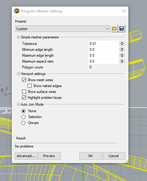


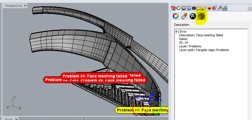
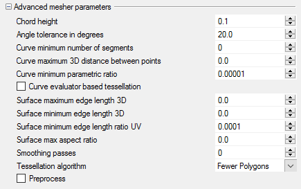
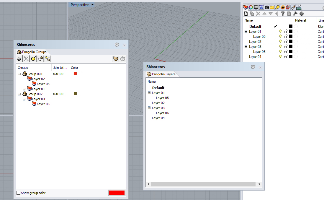

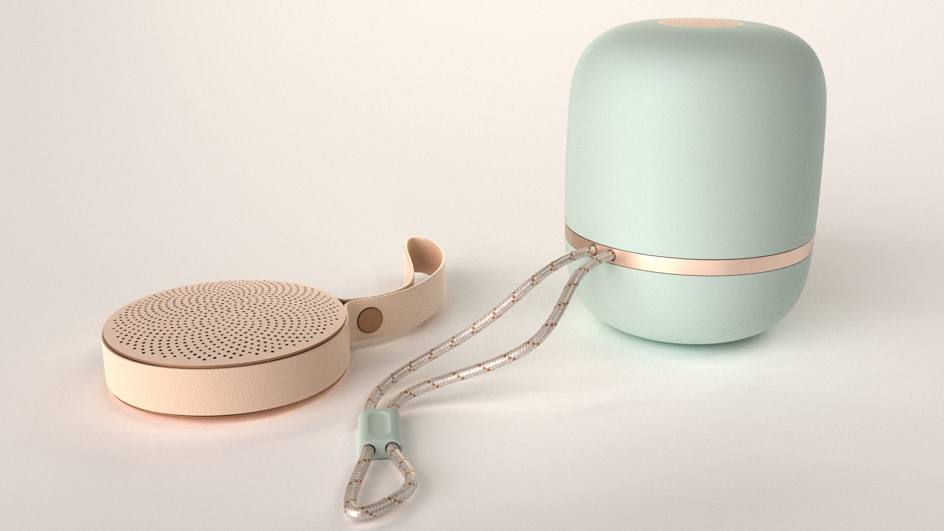
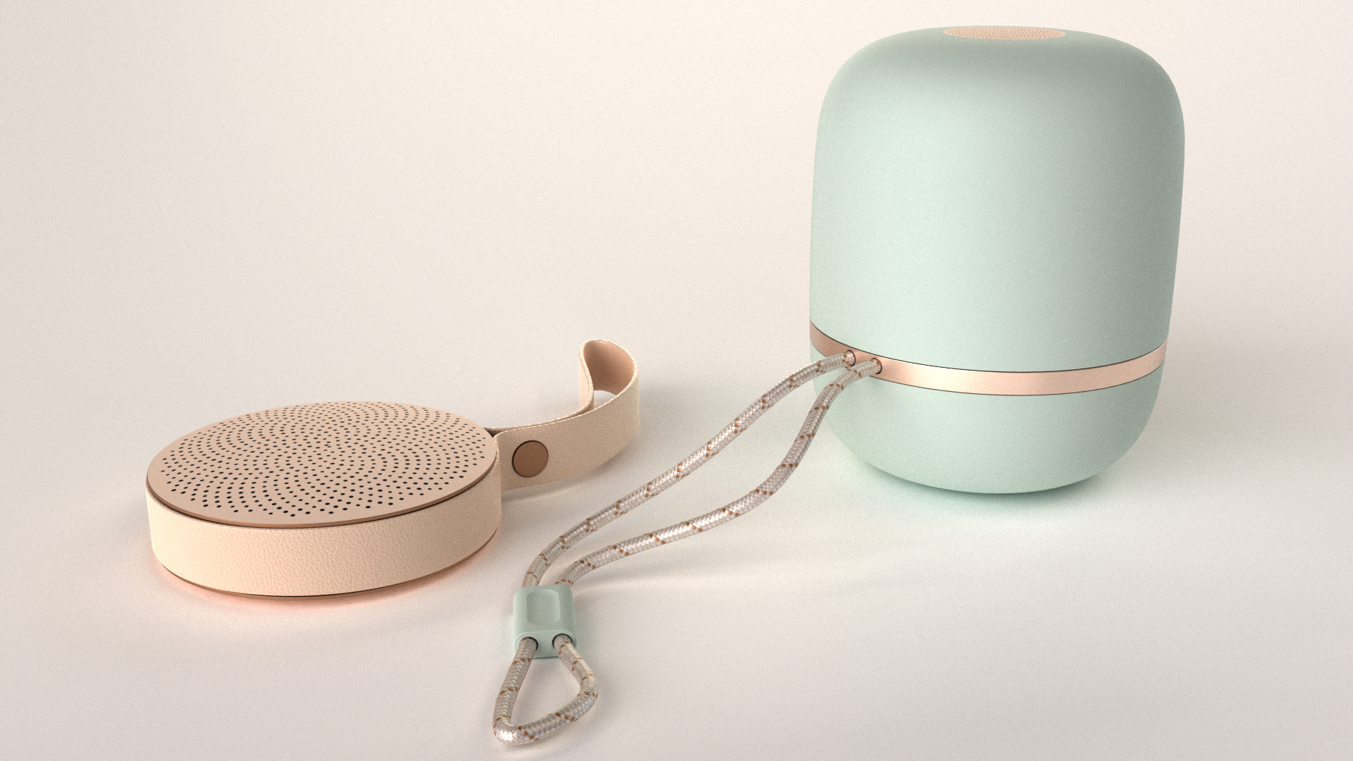
Girl in a jacket

What will you learn about

  • Modeling Aids
  • Construction Planes
  • Creating Curves
  • Creating Surfaces
  • Form Finding
  • Building Solids
  • Editing Solids
  • Apply Materials
## ## Table Tutorial (6 minutes) In this model, the Grid Snap setting is one-half of a grid line. Using this snap, you should be able to line objects up with each other.\ ### Creating Curves 1. If **Gumball** is on bold in the **Status Bar**, gumball is on. 2. Click to turn gumball off. 3. Click the cone and drag it. 4. Drag the objects around. You can drag in any viewport.\ The selected cone changes to the selection color.\ ![](https://www.rhino3d.com/en/docs/guides/modeling/rhino-7-getting-started2/start-014.png) ### Control point editing 1. On the **File** menu, click **Open**. 2. **Do not save** the changes. 3. In the **Open** dialog box, select **Start.3dm**. ### Extruding 1. Click the box to select it. 2. On the **Transform** menu, click **Copy**. 3. Click somewhere in the **Top** viewport.\ It usually helps to click a spot that relates to the object like the middle or near a corner.\ ![](https://www.rhino3d.com/en/docs/guides/modeling/rhino-7-getting-started2/start-018.png) 4. Click where you want the first copy.\ Zoom in closer if you like. 5. Click other places to make more copies of the box. 6. When you have enough copies, press Enter.\ ![](https://www.rhino3d.com/en/docs/guides/modeling/rhino-7-getting-started2/start-019.png) ![](https://www.rhino3d.com/en/docs/guides/modeling/rhino-7-getting-started2/start-020.png) ## Chair Tutorial (7 minutes) To create more objects, copy the shapes. Gumball displays a widget on a selected object, which is used to facilitate the direct editing. The gumball provides move, scale, and rotate transformations around the gumball origin. - Click the **Gumball **pane on the Status Bar.\ ![](https://www.rhino3d.com/en/docs/guides/modeling/rhino-7-getting-started2/gum_ball_status.png) ### Lofting - Drag gumball arrows to Move the object. - Drag scale handles (squares) to Scale the object in one direction. - Drag arcs to rotate the object. - Tap the Alt key after starting to drag to toggle copy mode. - Click a control handle to enter a numeric value. - Hold the Shift key during Scale to force 3-D scale. ### Control Point editing ![](https://www.rhino3d.com/en/docs/guides/modeling/rhino-7-getting-started2/01.png) Axis plane indicator ![](https://www.rhino3d.com/en/docs/guides/modeling/rhino-7-getting-started2/02.png) Free move origin ![](https://www.rhino3d.com/en/docs/guides/modeling/rhino-7-getting-started2/03.png) Menu location ### Revolving ![](https://www.rhino3d.com/en/docs/guides/modeling/rhino-7-getting-started2/04.png) Move X ![](https://www.rhino3d.com/en/docs/guides/modeling/rhino-7-getting-started2/05.png) Move Y ![](https://www.rhino3d.com/en/docs/guides/modeling/rhino-7-getting-started2/06.png) Move Z ### Obtaining a Closed Solid ![](https://www.rhino3d.com/en/docs/guides/modeling/rhino-7-getting-started2/07.png) Rotate X ![](https://www.rhino3d.com/en/docs/guides/modeling/rhino-7-getting-started2/08.png) Rotate Y ![](https://www.rhino3d.com/en/docs/guides/modeling/rhino-7-getting-started2/09.png) Rotate Z ## Lamp Tutorial (6 minutes) To create more objects, copy the shapes. Gumball displays a widget on a selected object, which is used to facilitate the direct editing. The gumball provides move, scale, and rotate transformations around the gumball origin. ### Helix Command 1. In the **Top** viewport, select the cone. 2. Drag the **red arrow** to move the object in the positive x or negative x-direction.\ ![](https://www.rhino3d.com/en/docs/guides/modeling/rhino-7-getting-started2/gb_cone-02.png) 3. Drag the **green arrow** to move the object in the positive y or negative y-direction.\  ![](https://www.rhino3d.com/en/docs/guides/modeling/rhino-7-getting-started2/gb_cone-03.png) 4. In the **Front** viewport, select the cone. 5. Drag the **blue arrow **to move the object in the positive z or negative z-direction.\ ![](https://www.rhino3d.com/en/docs/guides/modeling/rhino-7-getting-started2/gb_cone-04.png) 6. **Undo** enough times to get back to the original model. ### Pipe Command In this exercise you will drag objects with the gumball and tap the Alt key after starting to drag to toggle copy mode. 1. In the **Top** viewport, select the cone. 2. Drag the **red arrow** to move the object in the positive x or negative x direction.\ ![](https://www.rhino3d.com/en/docs/guides/modeling/rhino-7-getting-started2/gb_cone-11.png) 3. While still dragging, tap the Alt key.\ A plus + appears to the right of the red arrow.\ When you release the mouse button, a copy of the object is created.\  ![](https://www.rhino3d.com/en/docs/guides/modeling/rhino-7-getting-started2/gb_cone-12.png) ### Revolving Drag arcs to rotate the object. 1. In the **Top** viewport, select the cone. 2. Click and drag along blue arc to rotate cone.\ ![](https://www.rhino3d.com/en/docs/guides/modeling/rhino-7-getting-started2/gb_cone-15.png) 3. In the **Right** viewport, click and drag along green arc to rotate cone. 4. **Undo** enough times to get back to the original model.\ ![](https://www.rhino3d.com/en/docs/guides/modeling/rhino-7-getting-started2/gb_cone-16.png) #### Comtrol Point edit surface - Drag scale handles (squares) to Scale the object in one direction. - Click a scale control handles (squares) to enter numeric value. - Hold the Shift key during Scale to force 3-D scale. Change the view of your model ----------------------------- When you add detail to your models, you will need to see different parts of your model with different magnifications. You can use the view commands, the mouse, and the keyboard to change the view in a viewport. Each view corresponds to the view through a camera lens. The invisible target of the camera is located in the middle of the viewport. -------------------------------------------------------------------------------- # How Rhino 5 for Windows Finds the LAN Zoo Source: https://www.rhino3d.com/en/kb/rhino-5-how-rhino-finds-lan-zoo/ Where Rhino 5 for Windows looks for the name of its LAN Zoo server: the Windows Registry, then DNS. This article covers Rhino 5, which is no longer current. For Rhino 6 and later, see [How Does Rhino for Windows Find a LAN Zoo Server?](/docs/guides/licensing/lan-zoo/#how-does-rhino-for-windows-find-a-lan-zoo-server) When Rhino needs a license from a LAN Zoo server, it looks for the server's name in these locations, in this order: 1. The Current User hive of the Windows Registry. 2. The Local Machine hive of the Windows Registry. 3. Your Domain Name System (DNS) server, which it queries for the default LAN Zoo server name. ## Registry Lookup: Current User In `HKEY_CURRENT_USER`, both 32-bit and 64-bit Rhino look for the host name or IP address of your LAN Zoo server in this location: ``` Hive: HKEY_CURRENT_USER Key: Software\McNeel\Rhinoceros\5.0\License Manager Name: Server Type: REG_SZ Value: ``` ## Registry Lookup: Local Machine On 32-bit Windows, 32-bit Rhino looks in `HKEY_LOCAL_MACHINE` for the host name or IP address of your LAN Zoo server in this location: ``` Hive: HKEY_LOCAL_MACHINE Key: Software\McNeel\Rhinoceros\5.0\License Manager Name: Server Type: REG_SZ Value: ``` On 64-bit Windows, both 32-bit and 64-bit Rhino look in `HKEY_LOCAL_MACHINE` in this location: ``` Hive: HKEY_LOCAL_MACHINE Key: SOFTWARE\Wow6432Node\McNeel\Rhinoceros\5.0\License Manager Name: Server Type: REG_SZ Value: ``` ## Using DNS If Rhino can't find the name of the LAN Zoo server in the Windows Registry, it queries your DNS server for the default Zoo server host name, `__mcneel.__zoo5`. For example, if your company's domain is *mcneel.com*, add a DNS alias of `__mcneel.__zoo5.mcneel.com` that points to your LAN Zoo server. If a LAN Zoo server name is found in the Windows Registry, Rhino only tries to get a license from that location. For more on DNS lookup, see [How Does Rhino for Windows Find a LAN Zoo Server?](/docs/guides/licensing/lan-zoo/#how-does-rhino-for-windows-find-a-lan-zoo-server) -------------------------------------------------------------------------------- # Does Rhino Support VDI? Source: https://www.rhino3d.com/en/kb/does-rhino-support-vdi/ Which VDI (Virtual Desktop Infrastructure) platforms Rhino has been used on and what to expect for licensing and graphics performance. Rhino 8 and later support a number of VDI (Virtual Desktop Infrastructure) systems: - Amazon AppStream - Amazon WorkSpaces - Citrix XenApp - Citrix XenDesktop - Cloudalize - Itopia - Nutanix Frame - Vagon.io Rhino is not officially supported on AWS EC2, though you may be able to run it there through Remote Desktop. Getting good display performance over RDP is challenging, even with suitable NVIDIA cards, and we can't help you configure it. In summary, Rhino runs in the VDI environments listed above, but we can't help tune graphics performance in any of them. ## Rhino.Compute This list of supported VDI environments dates back to the start of Rhino 7, around the time [Rhino.Compute](https://developer.rhino3d.com/guides/compute/) was introduced. At that time, Rhino required Core-Hour Billing whenever it detected it was running on Windows Server. Because many VDI environments are detected as Windows Server, this caused problems for users who wanted standard seat-based licensing instead (a license key in standalone mode, the LAN Zoo, or the Cloud Zoo). ## Graphics Performance Our general advice is to try Rhino in these environments and see whether it works for you. - If you run into licensing problems, email tech@mcneel.com. - Unfortunately, we can't help troubleshoot performance problems. We don't have the specialized knowledge needed to configure graphics in virtual environments. This gets complicated quickly, and solutions tend to be platform-specific, each with its own configuration requirements. ## Next Steps Search the [Rhino Support Forum](https://discourse.mcneel.com) for existing answers, and don't hesitate to post a question of your own. The forum is monitored around the clock by McNeel staff around the world and by other Rhino experts, and your question and its answer become part of a searchable archive for future users. See also: [Rhino System Requirements](https://www.rhino3d.com/system-requirements/) -------------------------------------------------------------------------------- # Manually Removing a Rhino License Source: https://www.rhino3d.com/en/kb/manually-removing-a-rhino-license/ How to manually delete the Rhino license file on Windows and macOS, as a last resort when a license cannot be removed the normal way. Do this only as a last resort. Removing your license manually leaves it assigned in McNeel's records, and you will need to contact support to use it on another device. ## Windows By default, the ProgramData and AppData folders are hidden. To get to them, either turn on hidden files and folders in **Folder Options**, or type **%ProgramData%** or **%AppData%** in the File Explorer address bar. 1. Log in to the workstation as the Administrator or as a user with administrative rights. 1. Open File Explorer. 1. Paste one of these paths into the address bar: - Rhino 6 and later: *C:\ProgramData\McNeel\Rhinoceros\6.0\License Manager\Licenses* - Rhino 5: *C:\ProgramData\McNeel\Rhinoceros\5.0\License Manager\Licenses* 1. Delete the following file, if it exists: - Rhino 8: *868c63f5-3760-4a45-8600-5399cc57b47c.lic* - Rhino 7: *59ff75c9-9c71-4ef8-a290-6b590f3fc63a.lic* - Rhino 6: *55500d41-3a41-4474-99b3-684032a4f4df.lic* - Rhino 5: *60515f84-8f7f-41da-801d-1c87e32f88f5.lic* 1. Go to the following folder: `C:\Users\\AppData\Roaming\McNeel\Rhinoceros\\License Manager\Licenses` 1. Delete the same license file there, if it exists. 1. Right-click the Rhino shortcut and select **Run as administrator**. 1. Enter and validate your Rhino license key. ## macOS Make sure you have a record of your license key before you start. 1. Quit Rhino for Mac. 1. Open Finder. 1. Click **Go** → **Go to Folder** and enter the following folder: */Library/Application Support/McNeel/Rhinoceros/License Manager/Licenses* 1. Delete the license file in the *Licenses* folder. 1. Start Rhino. 1. Enter and validate your Rhino license key. -------------------------------------------------------------------------------- # Advanced Troubleshooting for License Manager Errors (Rhino 3 and 4) Source: https://www.rhino3d.com/en/kb/advanced-troubleshooting-for-license-manager-errors/ In-depth troubleshooting for the Rhino 3 and 4 'Unable to communicate with license manager' error, covering missing files, registry issues, and conflicting security software. This article covers Rhino 3 and 4, which are no longer current. For current licensing information, see [Licensing](/features/administration/licensing/). See also [Resolving "Unable to Communicate with License Manager" Errors](/kb/unable-to-communicate-with-license-manager/). ## Problem When you run either Rhino 3.0 or Rhino 4.0, you receive an "unable to communicate with license manager" error message. ## Cause Rhino cannot communicate with its license manager module. This can happen in both standalone and workgroup node installations, and has one of these causes: - Missing license manager files. - Missing Windows System Registry entries. - Missing runtime library support files. - An errant license manager that is still running. - A Windows Registry security issue. ## Solution 1: Get the Most Current Service Release Download the [current service release](/download/). A conflict with User Account Control can also cause this error when running Rhino 4 under Vista or Windows 7. Right-click the Rhino 4 icon and select **Run as administrator**. If this solves the problem, download and install Rhino 4 Service Release 7. ## Solution 2: Missing License Manager Files On English-language versions of Rhino, the license management modules are located in *C:\Program Files\Common Files\McNeel Shared\License Manager*. Rhino 3.0 and Rhino 4.0 use different license management modules: Rhino 3.0 uses **McNeelLM.exe**, and Rhino 4.0 uses **RhinoLM.exe**. If the module for your version of Rhino is missing, reinstall Rhino from your CD. RhinoLM is also used by plugins that run in both Rhino 4 and Rhino 5, such as Flamingo 2, Flamingo nXt, and Bongo 1.0/2.0. ## Solution 3: Uninstall and Reinstall If the license manager files or registry keys are missing, do a clean uninstall and reinstall: 1. Log in as the Administrator or an equivalent user. 2. Disable virus detectors and anti-spyware agents. 3. Uninstall Rhino and clean the system. 4. After uninstalling, navigate to *C:\Program Files\Common Files\McNeel Shared* and delete the License Manager subfolder. 5. Restart the computer. 6. Reinstall Rhino 4 using the product CD, then download and install the current service release if necessary. ## Solution 4: Missing Windows System Registry Entries If the license manager module is present but not registered, the Windows Registry may be missing the information Rhino needs to find it: 1. Log in as the Administrator or an equivalent user, and disable virus detectors and anti-spyware agents. 2. Navigate to *C:\Program Files\Common Files\McNeel Shared\License Manager*. ### Rhino 3.0 If the error occurs when running Rhino 3.0: 1. [Download](register-mcneellm.zip) and unzip the Register_McNeelLM.bat batch file into the same folder as McNeelLM.exe. 2. Double-click the batch file to run it. On Windows Vista, right-click it and select **Run as administrator**. The batch file echoes the results to the command line. To confirm this fixed the problem, run Rhino 3.0. ### Rhino 4 and 5 If the error occurs when running Rhino 4.0, or when running Flamingo or Bongo in Rhino 5: 1. [Download](register-rhinolm.zip) and unzip the Register_RhinoLM.bat batch file into the same folder as RhinoLM.exe. 2. Double-click the batch file to run it. On Windows Vista, right-click it and select **Run as administrator**. The batch file echoes the results to the command line. To confirm this fixed the problem, run Rhino. Alternatively, to reinstall RhinoLM without reinstalling Rhino 4, download, unzip, and run **rhinolm_20110309_x86.exe** from the [rhinolm_20110309.zip file](https://s3.amazonaws.com/mcneel/flamingo/nxt/rhinolm_20110309.zip). You must have rights to modify the registry to run it. ## Solution 5: Missing Runtime Library Support Files If the batch file returns an error, [download](https://www.microsoft.com/en-us/download/details.aspx?id=26347) and install the latest Microsoft runtime libraries and try again. ## Solution 6: An Errant License Manager Is Running Restart the computer. Even if the steps above worked, an errant license manager that is still running can keep causing the error. ## Solution 7: Comodo Internet Security Is Blocking COM [Comodo Internet Security](https://www.comodo.com/) can block COM interprocess communication between Rhino and the license manager. If you have Comodo running, disable this block: 1. Open Comodo Internet Security settings. 2. Click **Defense+ Settings**. 3. Click the **Monitor Settings** tab. 4. Uncheck **Protected COM Interfaces**. 5. Click **OK** to exit the dialog. Rhino 4 should now run properly. ## Solution 8: Windows Vista Registry Security Issue If the license manager module is present and registered, you might not have enough rights to read the Windows Registry. Using Registry Editor incorrectly can cause serious, system-wide problems that may require you to reinstall Windows to correct them. Robert McNeel & Associates and Microsoft cannot guarantee that any problems resulting from the use of Registry Editor can be solved. Use this tool at your own risk. For assistance, contact [McNeel Support](/support/). Run `Regedit.exe` and find the **RhinoLicenseManager.RhinoLicense** key in *HKEY_CLASSES_ROOT*: 1. Browse to *HKEY_LOCAL_MACHINE\Software\Classes*. 2. Right-click the **Classes** key, then click **Permissions**. 3. On the **Security** tab, check that **Group or User Names** lists at least four permission entries. The error is sometimes caused by missing permissions on the Classes registry key. If, and only if, permissions are missing, add them: 1. Click **Add**, type **Creator Owner**, click **OK**, select it, and clear all checkboxes in the Allow column. 2. Click **Add**, type **SYSTEM**, click **OK**, select it, and select **Full Control** in the Allow column. 3. Click **Add**, type **Administrators**, click **OK**, select it, and select **Full Control** in the Allow column. 4. Click **Add**, type **Users**, click **OK**, select it, and select **Read** in the Allow column. 5. Click **Advanced**, then in the Advanced Security Settings for Classes dialog, select **Replace all child object permissions with inheritable permissions from this object** and **Include inheritable permissions from this object's parent**. 6. Click **OK**. This may take several minutes. 7. In the Permissions for Classes dialog, click **OK**. If these steps don't work, run RegEdit as the System account using [PsExec](https://learn.microsoft.com/en-us/sysinternals/downloads/psexec). Download PsExec, and then run `PsExec -i -d -s c:\windows\regedit.exe`. You should now be able to run Rhino and communicate with the license manager. -------------------------------------------------------------------------------- # Changing a Rhino 5 for Mac License Key Source: https://www.rhino3d.com/en/kb/changing-a-rhino-5-for-mac-license-key/ How to replace a Rhino 5 for Mac evaluation license with a permanent one, or correct a license key that was entered incorrectly. This article covers Rhino 5, which is no longer current. For current licensing information, see [Licensing](/features/administration/licensing/). You may need to change your Rhino for Mac license key if: - You are running a 90-day evaluation and have purchased a permanent license. - You entered the wrong license key. ## Replacing an Evaluation with a Permanent License 1. Start Rhino for Mac. When the evaluation message appears, click **Change your license key**. 1. Enter your **Name**, **Organization** (optional), and **License Key**, and then click **Done**. 1. Restart Rhino, and then follow the instructions to validate your license. ## Changing an Incorrect License Key You can also use these steps to replace an evaluation license from inside Rhino. 1. Click the **Rhinoceros** menu. 1. Click **Preferences**. 1. Click **Licenses**. 1. Click **Change your license key**. 1. Enter your **Name**, **Organization** (optional), and **License Key**, and then click **Done**. 1. Restart Rhino, and then follow the instructions to validate your license. -------------------------------------------------------------------------------- # Educational Lab Licensing Source: https://www.rhino3d.com/en/docs/guides/licensing/educational-lab/ Learn what options exist to license Rhino for an educational lab, and find the best license type to fit your situation. You can manage a Rhino Educational Lab license in two ways. Pick the one that best fits your situation. **Use the [LAN Zoo](/docs/guides/licensing/lan-zoo/) on the school's private network.** This is the most common way to manage licenses across one or more labs, and it takes little maintenance. The LAN Zoo needs one computer to act as its host, normally the instructor's computer. Rhino is then installed on the lab computers manually or with an [automated install](/docs/guides/deployment/). **Use the [Cloud Zoo](/docs/guides/licensing/cloud-zoo/) for maximum flexibility.** You invite a group of people to a team that shares the licenses. Because someone has to keep the team's membership up to date, this works best for groups that don't change often, such as research labs or department staff. For a detailed comparison of licensing options, see [Choosing the best license management method](/features/administration/select-licensing-method/). You can switch from one licensing method to another, but it doesn't happen automatically. See [Changing Your Licensing Method](/docs/guides/licensing/changing-your-license/) for the steps. For educational pricing and eligibility, see [Educational Licensing](/docs/guides/licensing/educational/). For frequently asked licensing questions, see [Licensing](/features/administration/licensing/). -------------------------------------------------------------------------------- # I Cannot Find My Rhino License Key Source: https://www.rhino3d.com/en/kb/i-cannot-find-my-rhino-license-key/ What to do if you cannot locate your Rhino license key, including where older license keys were shipped and what replacement options exist. This article covers older versions of Rhino. For current licensing information, see [Licensing](/features/administration/licensing/). The Rhino license key is essential to establishing ownership of Rhino. License keys are a valuable part of the Rhino license. Keep them in a secure place. **If you can't find your license key, try the [license key finder](https://www.rhino3d.com/license/find/).** If you owned Rhino version 1, 2, or 3, the CD shipped in a pocket inside the back cover of the User's Guide, so check your bookcase. The User's Guide was about 1" (2.5 cm) thick, with a glossy black cover and a prominent Rhino logo on the front. Rhino version 4 shipped in a DVD case with a black label. Rhino version 5 shipped in a DVD case with a white label until eLIS was introduced. After that, Rhino 5 and later licenses were delivered by email. If you can't find your copy of Rhino and you registered it, we may be able to help find your license key. If you skipped registration, we won't have a record of it. We didn't track product serial numbers when we shipped them, so your order number won't help. Replacement CDs aren't available for Rhino versions 1 and 2, because of contractual obligations for core programming we licensed from a third party at the time. If you've searched everywhere for the physical product, replacement options are available for the full commercial version. For details, [email us](mailto:sales@mcneel.com) or [call](/support/) the nearest regional office. -------------------------------------------------------------------------------- # Installing Rhino 5 for Mac Source: https://www.rhino3d.com/en/kb/installing-rhino-5-for-mac/ Step-by-step instructions for installing Rhino 5 for Mac: getting an evaluation key, downloading the disk image, and validating a license key. This article covers Rhino 5, which is no longer current. For current licensing information, see [Licensing](/features/administration/licensing/). Follow these six steps to install Rhino 5 for Mac. If you run into problems, email **tech@mcneel.com** with a complete description of the problem. ## Step 1: Get a Download Link and 90-Day Evaluation License Key 1. Request a download link and license key. Enter your email address and click **Next**. We will send you an email message. 1. Check your email for a new message from Brian Gillespie titled **Welcome to Rhino 5 for Mac Evaluation**. ## Step 2: Download the Disk Image (DMG) 1. Open the email message. 1. Click the **Download Rhino 5 for Mac Evaluation** link to start the download. It takes a few minutes, depending on the speed of your internet connection. 1. Note the name of the downloaded file. It looks like **Rhinoceros_5.x.dmg** and is about 200 MB. 1. Write down the **License code** in item three of the email. You need it in step 5. ## Step 3: Open the Disk Image (DMG) 1. In **Finder**, browse to your Downloads folder and find the Rhinoceros package you just downloaded. 1. Right-click the installer and choose **Open**. 1. Read the short license agreement and click **Agree**. Wait while the package is opened and verified. 1. Drag Rhinoceros.app into the Applications folder. 1. Find the Rhinoceros disk image on your desktop. Right-click it and choose **Eject Rhinoceros**. ## Step 4: Launch Rhinoceros 1. Open **Launchpad** from your Dock, find the Rhinoceros application, and start it. Wait while it is verified, and then click **Open**. If you don't get the option to open Rhinoceros, see [this support topic](https://wiki.mcneel.com/rhino/mac/not-downloaded-from-the-appstore). ## Step 5: Enter Your License Key 1. Click **Enter a License**. 1. Enter your **Name**, **Organization** (optional), and the **License Key** from your email message. 1. Click **Done**. ## Step 6: Validate and Register Your License 1. When the Rhino splash screen opens, click **New Model**. 1. When **Welcome to License Validation** opens, click **Continue**. 1. Enter your email address in both fields and click **Continue**. 1. Register your license. 1. Click **Continue**. 1. Click **Close** to finish. -------------------------------------------------------------------------------- # Installing Rhino in Multiple Locations Source: https://www.rhino3d.com/en/kb/installing-rhino-on-multiple-computers/ What the Rhino license agreement says about running Rhino on more than one computer, and how to share licenses. The [Rhino license agreement](https://www.rhino3d.com/eula/) limits the number of Rhino sessions running at the same time to the number of licenses you own. It states: > "The License is installed on a computer or virtual machine you own, lease, rent, or license. The number of login sessions running the Software at the same time does not exceed the number of licenses you own." It also states: > "A single user can run multiple sessions of Rhino on the same computer or virtual machine with a single (1) User license. Each additional computer or user will require an additional User license." In practice: - One license covers one user on one computer or virtual machine, including several Rhino sessions on that computer. - Each additional computer or user needs an additional license. - To manage several licenses across several computers and users, add your licenses to the [Cloud Zoo](/docs/guides/licensing/cloud-zoo/) or the [LAN Zoo](/docs/guides/licensing/lan-zoo/), as the license agreement recommends. -------------------------------------------------------------------------------- # Resolving "Unable to Communicate with License Manager" Errors Source: https://www.rhino3d.com/en/kb/unable-to-communicate-with-license-manager/ Fixes for the Rhino 3 or 4 'Unable to communicate with license manager' error, including reinstalling the license manager and repairing Rhino 4. This article covers Rhino 3 and 4, which are no longer current. For current licensing information, see [Licensing](/features/administration/licensing/). ## Did You Just Remove the Rhino 5 Beta? Download and install the [Microsoft Visual C++ 2005 Service Pack 1 Redistributable Package MFC Security Update](https://www.microsoft.com/en-us/download/details.aspx?id=26347). After installation, Rhino 4 should be able to communicate with the license manager properly. ## Did You Just Uninstall Rhino 4 While Running Rhino 5? Flamingo nXt, Bongo 1.0/2.0, and Rhino 4 use a common file called RhinoLM. Uninstalling Rhino 4 removes RhinoLM, so Flamingo nXt and Bongo 1.0/2.0 can no longer run in 32-bit or 64-bit Rhino 5. To reinstall RhinoLM without reinstalling Rhino 4, download, unzip, and run **rhinolm_20110309_x86.exe**, which is in this [rhinolm_20110309.zip file](https://s3.amazonaws.com/mcneel/flamingo/nxt/rhinolm_20110309.zip). You must have rights to modify the registry to run it. If access is denied, ask a computer administrator to log in with an elevated account and run it. On Windows Vista, right-click the file and select **Run as administrator**. ## Are You Running Windows Vista or Windows 7? Make sure you're running Rhino 4.0 SR9. Start Rhino 4, and then click **Help** → **Check for Updates**. ## Reinstall Rhino 4 If none of the above applies, your Rhino 4 installation may be damaged. To repair it: 1. Uninstall Rhino 4. You may need to remove several "Rhinoceros 4.0 SRx" items. 2. Delete the "License Manager" folder under *C:\Program Files\Common Files\McNeel Shared* (32-bit) or *C:\Program Files (x86)\Common Files\McNeel Shared* (64-bit). 3. Install Rhino 4 again. 4. Start Rhino 4, and then click **Help** → **Check for Updates**. 5. Download and install the latest service release if required. ## Still Not Working? If none of these steps work, see [Advanced Troubleshooting for License Manager Errors](/kb/advanced-troubleshooting-for-license-manager-errors/). -------------------------------------------------------------------------------- # Rhino 5 License Validation Source: https://www.rhino3d.com/en/kb/rhino-5-license-validation/ How Rhino 5 license validation works, including upgrading from a previous version, validating offline, and installing Rhino for disk imaging. This article covers Rhino 5, which is no longer current. For current licensing information, see [Licensing](/features/administration/licensing/). Rhino 5 introduced a license validation system aimed at making it easier to recover lost or stolen license keys. License validation associates your license with your email address (or email domain, in the case of a Lab License) and, for upgrade licenses, your previous license key. The Rhino license agreement lets you install Rhino on multiple computers at once, as long as the license is in use on only one computer at a time. The validation system lets you install your license on multiple computers, so long as you validate your license with the same information each time. ## Upgrading from Previous Versions When you upgrade Rhino from a previous version, license validation associates the license from your previous version of Rhino with the license you are upgrading to. A previous-version license can be used to upgrade only one Rhino 5 license. For example, if a company owns four Rhino 4 licenses and wants to upgrade to Rhino 5, each upgrade installation must be associated with a different Rhino 4 license for validation to succeed. ## The Validation Process After installing Rhino, you have a 30-day grace period to complete the validation process. Rhino displays the License Validation Wizard. Follow the on-screen instructions to validate your license. If you get an error during license validation, contact [McNeel Technical Support](/support/) and include the error description. ## Validating Offline If your computer is not connected to the internet, the License Validation Wizard explains how to validate using a web browser on another computer: 1. Visit the validation website given by Rhino. 2. Enter your email address and license key. 3. If required, enter a license key for a previous version of Rhino. 4. Print or write down the validation code that appears. 5. Return to the computer that does not have an internet connection. It must be offline for offline validation to work, so disconnect it from wireless or unplug the network cable. 6. Start Rhino 5. 7. Enter your validation code in the Validation Wizard and click **Next**. Rhino is now validated. ## Installing Rhino for Imaging In a standalone Rhino installation (commercial, educational, or educational lab), validation is tied to a specific computer. When you image a computer and push the image to a new computer, Rhino requires validation again on the new computer. To avoid this, consider these options: - **(Recommended)** Use the free floating license manager, the LAN Zoo, on a server to manage the Lab License key and validate it once. Deploy Rhino as a network install on the computer you are setting up as the disk image, and then push that image to all computers. - Log in as a local administrator on each imaged computer, start Rhino, and go through license validation there. This is time consuming, and we don't recommend it unless you can't recreate the image with the hard drive's serial number. -------------------------------------------------------------------------------- # Rhino 5 Validation Fails Even After Reset Source: https://www.rhino3d.com/en/kb/rhino-5-validation-fails-even-after-reset/ How to delete the Rhino 5 license (.lic) file when validation keeps failing, even after McNeel Sales has reset the license. This article covers Rhino 5, which is no longer current. For current licensing information, see [Licensing](/features/administration/licensing/). If validation fails with a message about an invalid email address, call [McNeel Sales](https://www.rhino3d.com/sales/) in your region (US 206-545-7000). If validation fails even after Sales has reset your license, or you are prompted to enter an upgrade key that you don't have, you may have typed your Rhino 5 license key incorrectly. To fix this, delete the LIC file using either method below. ## Method 1 1. Close Rhino. 2. Delete the LIC file in the *C:\ProgramData\McNeel\Rhinoceros\5.0\License Manager\Licenses* folder. The file name is similar to *12456787-8f7f-41da-801d-1c87e32f88f5.lic*. 3. Start Rhino 5. 4. Enter your license key again. ## Method 2 1. Download [DeleteRhinoLicense.exe](https://s3.amazonaws.com/mcneel/rhino/5.0/DeleteRhinoLicense/DeleteRhinoLicense.exe) onto your desktop. 2. Run **DeleteRhinoLicense**. 3. Start Rhino 5. 4. Enter your Rhino 5 license key. 5. Restart Rhino 5. 6. Validate your license. If you still have problems, contact [McNeel Technical Support](/support/). -------------------------------------------------------------------------------- # Rhino 5: Error "_mcneel._zoo5" Source: https://www.rhino3d.com/en/kb/rhino-5-error-mcneel-zoo5/ How to fix a damaged Rhino 5 license file that shows an error mentioning '_mcneel._zoo5' the first time Rhino 5 runs after installation. This article covers Rhino 5, which is no longer current. For current licensing information, see [Licensing](/features/administration/licensing/). ## Problem Rhino 5 cannot run and shows an error message about "_mcneel._zoo5". This happens the first time Rhino 5 runs after it is installed. ## Cause An unknown Windows problem has damaged the Rhino license file on your computer. ## Solution 1. Delete the Rhino license file on your computer, as described in [Manually Removing a Rhino License](/kb/manually-removing-a-rhino-license/). 2. Start Rhino 5. A message about a missing license file appears. 3. Choose one of these options: - If you have a Rhino 5 license key for this computer, click **Enter a License** and enter your license key. - If you use a LAN Zoo floating license server, select **Use a Zoo** and enter the LAN Zoo server name or IP address. - If you don't have a Rhino 5 key, click **Evaluate**. -------------------------------------------------------------------------------- # Rhino 5: Error "Rhino is Unable to Connect to ZooClient.dll" Source: https://www.rhino3d.com/en/kb/rhino-5-unable-to-connect-to-zooclientdll/ How to fix the Rhino 5 for Windows error 'Rhino is unable to connect to ZooClient.dll', most often seen on Rhino 5 64-bit under Windows 8. This article covers Rhino 5, which is no longer current. For current licensing information, see [Licensing](/features/administration/licensing/). ## Problem Rhino 5 shows the message "Rhino is unable to connect to ZooClient.dll. Rhino will not run." In known cases, this happens only with Rhino 5 64-bit on Windows 8. Rhino 5 32-bit is not affected. ## Cause Rhino 5 doesn't have the permissions it needs to interact with ZooClient.dll. ## Solution 1 Download and install the [Rhino 5 full version](/download/). It includes an updated installer and the current service release, which the original DVD release of Rhino 5 did not. ## Solution 2 1. Right-click the Rhino 5 shortcut on the desktop and select **Properties**. The changes apply to the Rhino 5 executable, not just the shortcut. 2. On the **Compatibility** tab, select **Windows 7** compatibility mode. 3. Check **Run this program as an administrator**. 4. Click **OK**. -------------------------------------------------------------------------------- # Rhino 5: License Manager Initialization Failed with Error -200 or -300 Source: https://www.rhino3d.com/en/kb/rhino-5-license-manager-error-200-or-300/ How to fix the Rhino 5 'License manager initialization failed with error -200 or -300' message by reinstalling the Rhino 5 program components. This article covers Rhino 5, which is no longer current. For current licensing information, see [Licensing](/features/administration/licensing/). ## Problem Rhino 5 displays a "License manager initialization failed" error, with code -200 or -300, and will not run. ## Cause Unknown. ## Solution 1. Uninstall the four Rhino 5 program components using the Windows Control Panel: **Rhinoceros 5**, **Rhinoceros 5 (64-bit)**, **Rhinoceros 5 Help Media**, and **Rhinoceros 5 Language Pack Installer**. 2. Run Windows **Check for Updates** to install all available Windows updates. 3. Download and install the latest full version of Rhino 5 from [rhino3d.com/download](https://www.rhino3d.com/download/rhino/5/latest). If the error persists after reinstalling, run **Repair** on Rhinoceros 5 (64-bit) in Programs and Features. One user reported that this corrected the error. -------------------------------------------------------------------------------- # Rhino V3 Asks for a Hardware Lock Source: https://www.rhino3d.com/en/kb/rhino-3-hardware-lock-for-asian-language-windows/ Why Rhino V3 asks for a hardware lock when installed on a computer running Windows in an Asian language, and how to avoid it. This article covers Rhino V3, which is no longer current. For current licensing information, see [Licensing](/features/administration/licensing/). When Rhino V3 is installed or run on a computer running Windows in an Asian language, Rhino requires a hardware lock. Our Asian distributors required this. You have two options: - To keep Windows in the Asian language, use a parallel-port or USB hardware lock. These are available from Robert McNeel & Associates, and are included with copies of Rhino V3 sold in Asia. - In Control Panel, open **Regional and Language Options**. Set both **Standards and formats** and, on the **Advanced** tab, **Language for non-Unicode programs** to US English or another Western European language. Rhino then no longer asks for a hardware lock. In Rhino V4, a license validation system replaced this hardware lock system. -------------------------------------------------------------------------------- # "Application Has Failed to Start" Error Source: https://www.rhino3d.com/en/kb/zoo4-runtimeerror/ Solving the "Application has failed to start..." error. Zoo 4.0 was the license manager for Rhino 4, which reached end of life long ago. This article is kept for historical reference. For current LAN Zoo licensing, see the [LAN Zoo guide](/docs/guides/licensing/lan-zoo/). ## Question I am trying to install the Zoo. But, I keep getting the following error when I try to run the Zoo Console. ![Application has failed to start error](https://www.rhino3d.com/en/kb/zoo4-runtimeerror/runtime-error.jpg) ## Answer You can receive this message if your Windows system does not have the most up-to-date Microsoft Runtime libraries installed. Download and install the following: [Microsoft Visual C++ 2005 Service Pack 1 Redistributable Package MFC Security Update](https://www.microsoft.com/en-us/download/details.aspx?id=26347) Make sure you download and install the 32-bit, or x86, redistributable package. The file name to download is **vcredist_x86.exe (2.6 MB)**. -------------------------------------------------------------------------------- # "CD Key Addition Request Denied by the Server" Error Source: https://www.rhino3d.com/en/kb/zoo4-checkinerror/ Solving the "CD Key addition request denied by the server..." error. Zoo 4.0 was the license manager for Rhino 4, which reached end of life long ago. This article is kept for historical reference. For current LAN Zoo licensing, see the [LAN Zoo guide](/docs/guides/licensing/lan-zoo/). ## Question We have a user running Rhinoceros that gets its license from our Zoo server. The user can check out the license and work off-site. However, when he tries to check the license back in again, he gets the following error: *CD Key addition request denied by the server. Contact your system administrator.* ![CD Key addition request denied error](https://www.rhino3d.com/en/kb/zoo4-checkinerror/zoo-checkin-failed.jpg) This has always worked in the past. I went through the troubleshooting documentation, but have found nothing to help resolve this issue. ## Answer Here are some reasons you might get this error: 1. License check out is not enabled on the Zoo server. If this is not enabled, then you will also not be able to check in licenses. 1. The checked out license has been manually checked in from the Zoo console. Thus, the Zoo does not know the license is checked out (anymore). 1. The system really has a standalone license. When you run CheckInLicense, the Zoo will try to add the CD key to its license pool and fail if the license already exists. Walk over to the Zoo console and see if the workstation in question still has a license checked out. If it does not, then you will need to delete Rhino’s license key, **RHINO.KEY**, found in Rhino's SYSTEM folder and then restart Rhino. If the license is still checked out on the Zoo, then run through the [Zoo Troubleshooting](/kb/zoo4-troubleshooting/) tips to see what has changed on the workstation. -------------------------------------------------------------------------------- # "Failed to Write to Client Mailslot" Error Source: https://www.rhino3d.com/en/kb/zoo4-writemailsloterror/ Solving the "Failed to write to client mailslot..." error. Zoo 4.0 was the license manager for Rhino 4, which reached end of life long ago. This article is kept for historical reference. For current LAN Zoo licensing, see the [LAN Zoo guide](/docs/guides/licensing/lan-zoo/). ## Question I have installed the Zoo on one of our servers. But none of my Rhino clients can obtain a license. When I look in the Zoo's log file, I see the following errors: ```