Learn how to use FilletSrf to create beautiful transitions

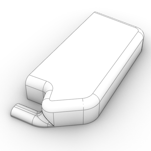
In this tutorial, we will model an oil drainage jerrycan using a workflow that involves surface fillets to create base and transition surfaces. Functional products, like this oil drainage jerrycan, don’t require G2 continuous surfaces. Therefore only G1 (rolling ball) fillets are used. Since this is a rotation mold product, only the outer surfaces need to be modeled.
We will use the
![]() FilletSrf
command since it can handle both surfaces that share an edge as well as surfaces that are not connected. This enables you to control arc-like transitions between surfaces that do not meet.
FilletSrf
command since it can handle both surfaces that share an edge as well as surfaces that are not connected. This enables you to control arc-like transitions between surfaces that do not meet.
Step 1 - Creating the base volume
Download and open the oil_drainage_jerrycan.3dm.
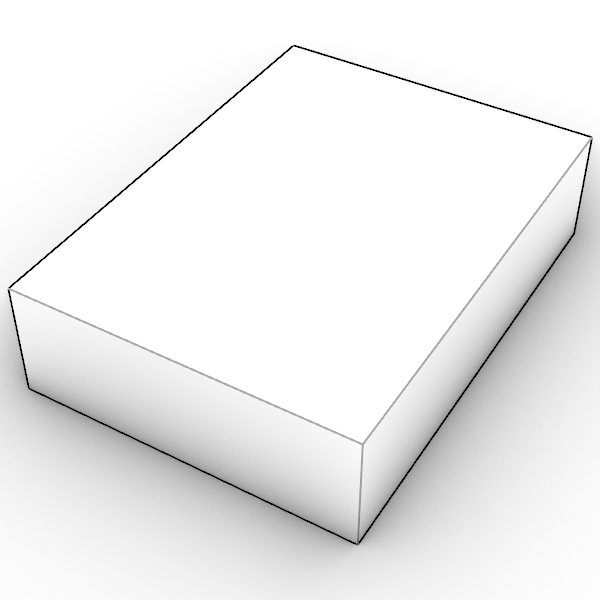
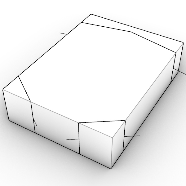
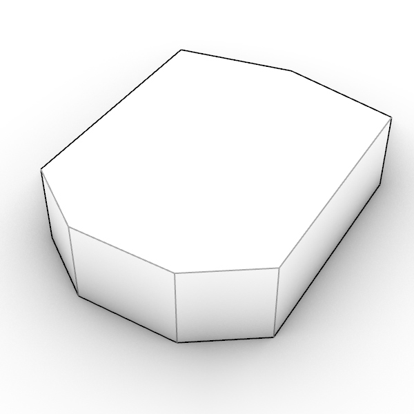
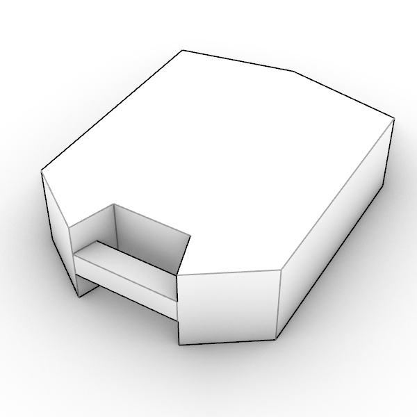
Turn on layer 1a where you’ll find the bounding box volume of the product. We start by cutting off parts of this box using the Gumball. Select the curves on layer cutting curves and use Gumball’s cut handle to slice through the box in Z directions. Hold Shift to cut in both directions (1b). Delete the smaller slices (1c).
Step 2 - Creating the handle cutout
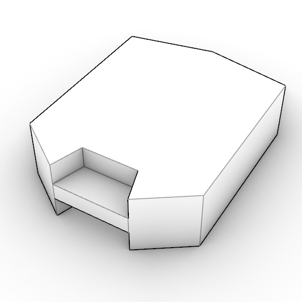
Using the curves on layer handle curves, use Gumball on the closed curves to cut out parts. There are two closed curves; one is cut in positive and the other in negative Z direction (2a).
There is one open curve that is flush with the new cutout. Start
![]() PushPull
, select the area of the handle to cutout, and push it through the volume to make the cutout (2b).
PushPull
, select the area of the handle to cutout, and push it through the volume to make the cutout (2b).
Step 3 - Surface Fillets
Start
![]() FilletSrf
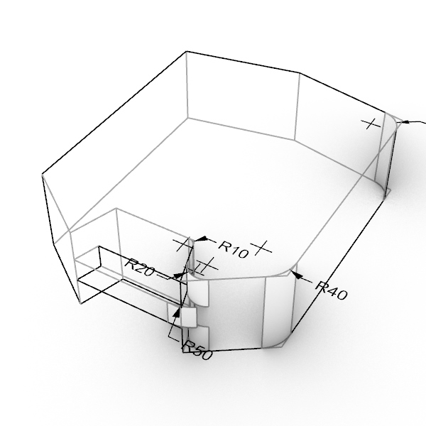
and click on the two surfaces where the 10mm concave fillet will be placed. A dialog will open that allows you to interactively change the radius with a slider. Although the radius is in this case known, try using the slider to change the radius and see it update in real time.
FilletSrf
and click on the two surfaces where the 10mm concave fillet will be placed. A dialog will open that allows you to interactively change the radius with a slider. Although the radius is in this case known, try using the slider to change the radius and see it update in real time.
Unless stated otherwise, make sure that the option Trim is kept On and Extend is kept Off during this tutorial.

Now add fillets to the handle of radius 12.5 (3b).
![]() Explode
the model and
Explode
the model and
![]() Split
the surfaces by isocurve using Intersection Osnap, and delete the surface parts that are not needed. This should end in the result seen in image 3c.
Split
the surfaces by isocurve using Intersection Osnap, and delete the surface parts that are not needed. This should end in the result seen in image 3c.
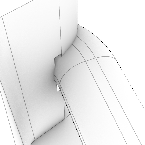
Now
![]() ExtendSrf
the large corner fillet as indicated in image 3d.
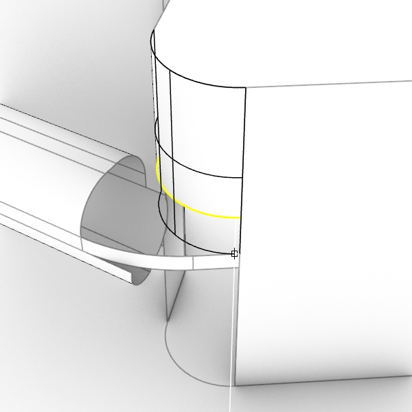
Next, construct the surfaces in step 3e with
ExtendSrf
the large corner fillet as indicated in image 3d.
Next, construct the surfaces in step 3e with
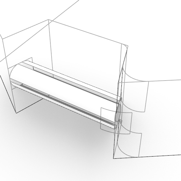
![]() Sweep1
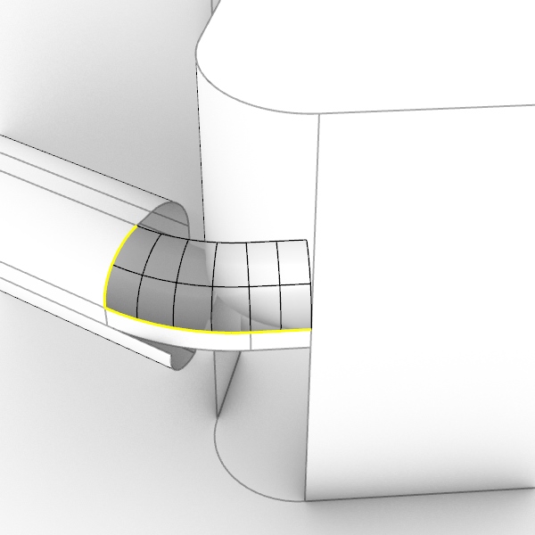
Start on the front to create the first surface (3e), then work your way to create the other surfaces, using the last created surface edge as rail for the next Sweep, resulting in 3f.
Sweep1
Start on the front to create the first surface (3e), then work your way to create the other surfaces, using the last created surface edge as rail for the next Sweep, resulting in 3f.
Use
![]() FilletSrf
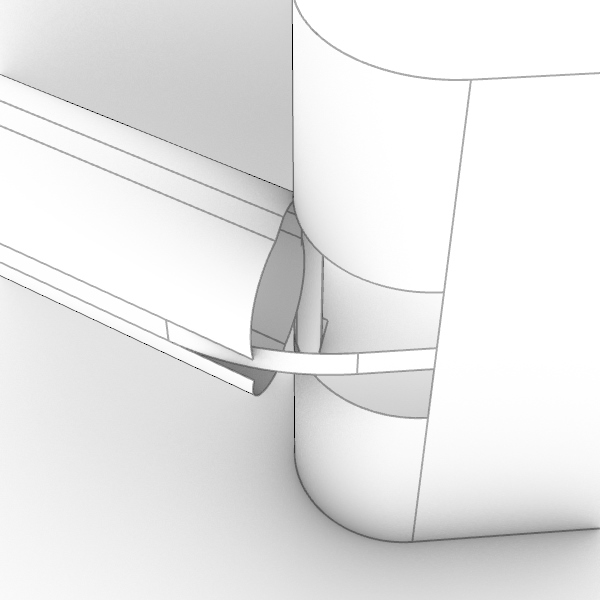
with a radius of 10mm to create the transition between the handle and body surfaces.
Next, use the fillets created in previous steps to trim the surfaces that have been filleted (3g).
FilletSrf
with a radius of 10mm to create the transition between the handle and body surfaces.
Next, use the fillets created in previous steps to trim the surfaces that have been filleted (3g).
If the fillets are made correctly, you can use them directly to trim the filleted surfaces. If this fails, duplicating the edges of the fillets can help them to be used as trimming objects instead.
<script>
    var parser = new DOMParser();
    var href = "https://docs.mcneel.com/rhino/8/help/en-us/unfurl/dupedge.htm"
    var scriptTag = document.getElementsByTagName('script');
    scriptTag = scriptTag[scriptTag.length - 1];
    var parentTag = scriptTag.parentNode;

    function addPreviewDiv(parent){
        const previewElement = document.createElement("span");
        previewElement.classList.add("tooltip");
        previewElement.classList.add("arrow-top");

        const iframeElement = document.createElement("iframe");
        iframeElement.src = href;
        iframeElement.style.width = "100%";
        iframeElement.style.height = "100%";
        iframeElement.style.border = "none";
        previewElement.appendChild(iframeElement);

        parent.appendChild(previewElement)
    }

    addPreviewDiv(parentTag)

</script>
Step 4 - Finalizing the base surfaces
So far, our mode is still symmetrical along 2 axis, therefore we only made fillets on one quarter of the model.
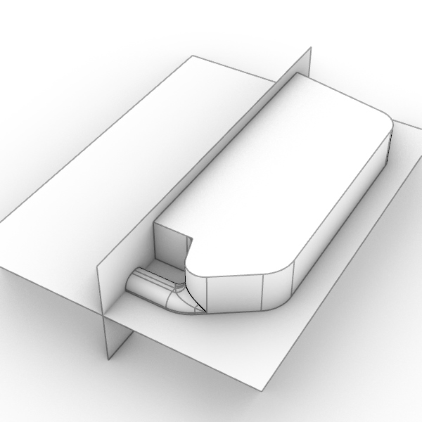
In
view, create two planes with
![]() CutPlane
along the X and Y axes, and use these surfaces to
CutPlane
along the X and Y axes, and use these surfaces to
![]() Trim
the three quarters of the model that are no longer needed.(4a)
Trim
the three quarters of the model that are no longer needed.(4a)
Now, create a series of fillets along the top edge (radius 15mm). Notice that the last surface fillet on the side opposite to the handle will not trim the vertical surface. To fix this, use
![]() ExtendSrf
to extend the surface and
ExtendSrf
to extend the surface and
![]() Trim
it with the vertical cutplane created in step 4a.
Trim
it with the vertical cutplane created in step 4a.
![]() Join
the resulting fillets and trim the top surface to finalize the (quarter)shape (4b).
Join
the resulting fillets and trim the top surface to finalize the (quarter)shape (4b).
![]() Mirror
the complete shape from the previous step over the Y-axis and join the result.
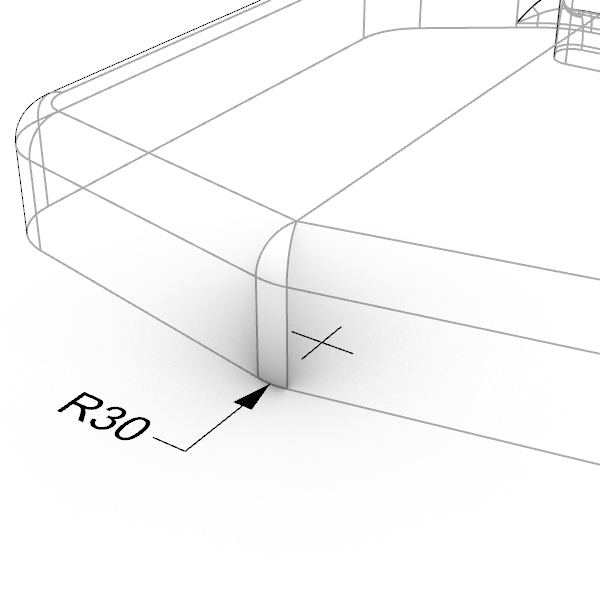
Make a 30mm surface fillet between the two parts where there is still a sharp edge. This time disable the Trim option in FilletSrf as well. After creating the two fillets, use these surfaces to
Mirror
the complete shape from the previous step over the Y-axis and join the result.
Make a 30mm surface fillet between the two parts where there is still a sharp edge. This time disable the Trim option in FilletSrf as well. After creating the two fillets, use these surfaces to
![]() Trim
the surfaces that were just filleted.
Trim
the surfaces that were just filleted.
![]() Join
the resulting surfaces into one open polysurface (4c).
Join
the resulting surfaces into one open polysurface (4c).
Select the resulting polysurface, run
![]() Mirror
and use the command option Z to mirror over the Z-axis.
Mirror
and use the command option Z to mirror over the Z-axis.
![]() Join
the two objects into one. This should result in a closed polysurface (Solid).
Join
the two objects into one. This should result in a closed polysurface (Solid).

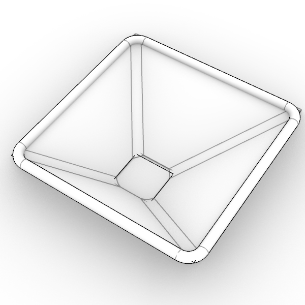
Step 5 - Creating the funnel
Select the two rectangles in layer funnel curves and
![]() Loft
these curves and make a
Loft
these curves and make a
![]() PlanarSrf
from the smallest rectangle (5a).
PlanarSrf
from the smallest rectangle (5a).
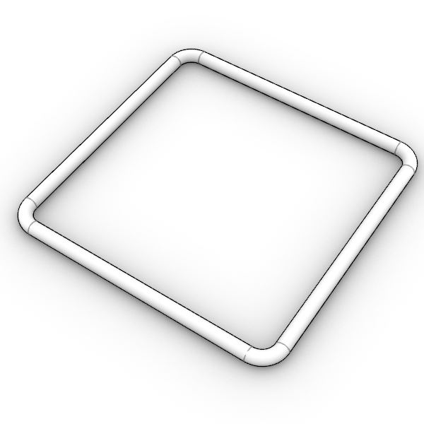
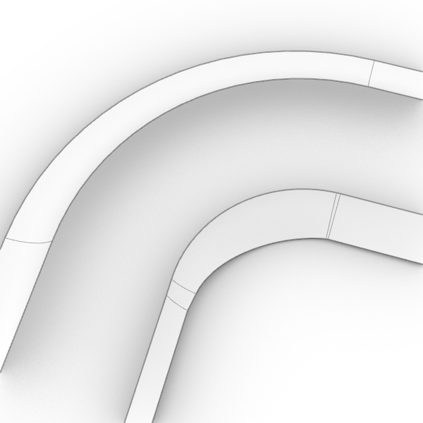
Next make a
![]() Pipe
around the curve in layer pipe curve, radius 5mm (5b).
Pipe
around the curve in layer pipe curve, radius 5mm (5b).
Turn on History recording: Right-clicking Record History in the StatusBar, and select “Always Record History”.
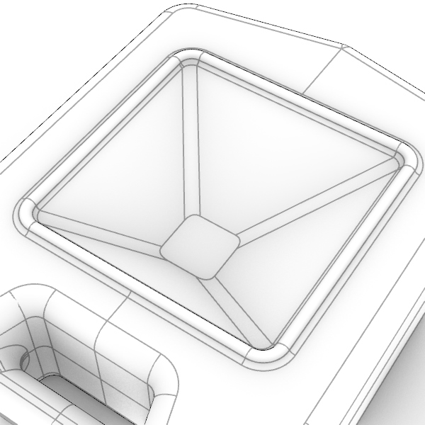
Use
![]() FilletSrf
to create the fillets in the corners of the funnel. This time, disable Trim and enable Extend. Try to match the corner fillets’ size with the pipe’s corners. The corners on the steeper side need a different radius than the other side. I used a radius of 15 for the steeper side and 20 for the other. Notice that these fillets don’t precisely line up with the corners in our piped curve yet.
To better align the funnel with the piped curve, select the loft surface and nudge it down in top view until satisfied (5c). I moved the surface down 3mm. Notice that due to the history recording, the fillets will update. This will however only work when Trim in the FilletSrf dialog has been disabled.
FilletSrf
to create the fillets in the corners of the funnel. This time, disable Trim and enable Extend. Try to match the corner fillets’ size with the pipe’s corners. The corners on the steeper side need a different radius than the other side. I used a radius of 15 for the steeper side and 20 for the other. Notice that these fillets don’t precisely line up with the corners in our piped curve yet.
To better align the funnel with the piped curve, select the loft surface and nudge it down in top view until satisfied (5c). I moved the surface down 3mm. Notice that due to the history recording, the fillets will update. This will however only work when Trim in the FilletSrf dialog has been disabled.

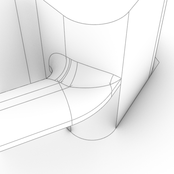
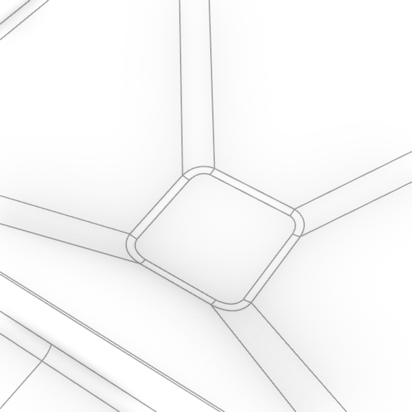
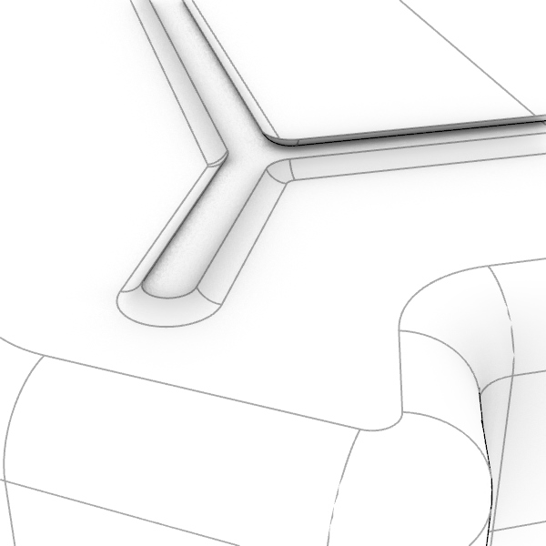
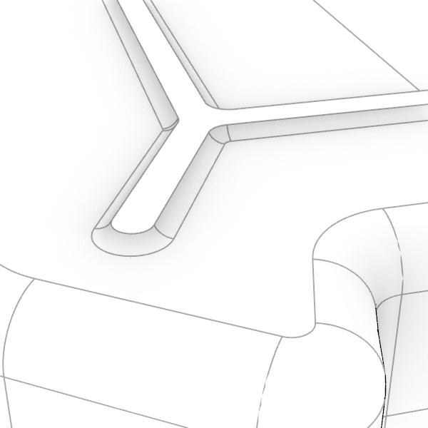
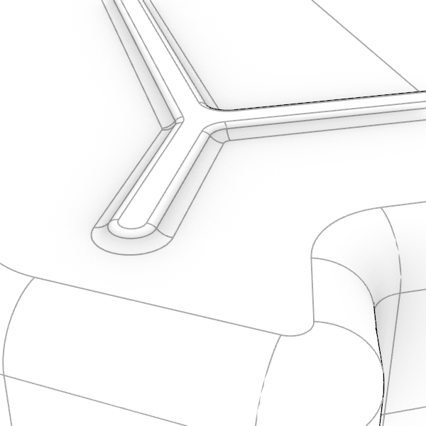
Make connecting fillets between the pipe and the base solid and between the pipe and the funnel of radius 5mm. Make sure the Extend option is turned off again. To create all the fillets of the pipe to the funnel, at each corner you will end up with one bigger and two smaller surface fillets(5d).
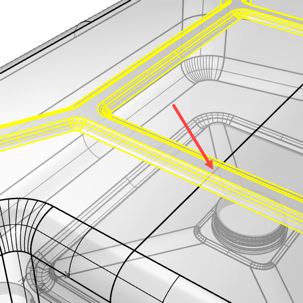
After making all the fillets, select the two fillet chains and
![]() Join
them into two polysurfaces. Select the outer chain and
Join
them into two polysurfaces. Select the outer chain and
![]() Trim
the inside of the base shape. Next, add the inner chain to the selection and trim both the pipe as well as the funnel.
Trim
the inside of the base shape. Next, add the inner chain to the selection and trim both the pipe as well as the funnel.
![]() Join
the resulting surfaces and polysurfaces into a closed polysurface (5e).
Join
the resulting surfaces and polysurfaces into a closed polysurface (5e).
For the last part of this step, we will use
![]() FilletEdge
with a radius 3. In the Command Line, set Railtype=DistBetweenRails to make the fillet at the bottom of the funnel (check image 5f).
FilletEdge
with a radius 3. In the Command Line, set Railtype=DistBetweenRails to make the fillet at the bottom of the funnel (check image 5f).
Step 6 - Adding screw details
Modeling the screw parts goes beyond the scope of this tutorial. These parts are therefore provided as is. Use
![]() BooleanUnion
to combine the outlet with the main body and
BooleanUnion
to combine the outlet with the main body and
![]() BooleanDifference
to subtract the two smaller threads from the main body.
BooleanDifference
to subtract the two smaller threads from the main body.

Step 7 - Adding bottom support
In this last step, we will use
![]() FilletSrfCrv
to create a fillet between the bottom surface and a curve. This will allow us to create a fillet tangent to the surface connecting to the curve. Imagine a ball running over the surface along the curve. For best results, explode the curve and make a FilletSrfCrv to each curve (7a).
FilletSrfCrv
to create a fillet between the bottom surface and a curve. This will allow us to create a fillet tangent to the surface connecting to the curve. Imagine a ball running over the surface along the curve. For best results, explode the curve and make a FilletSrfCrv to each curve (7a).
Make a
![]() PlanarSrf
with the curves and join this with the created fillets (7b).
PlanarSrf
with the curves and join this with the created fillets (7b).
Create a fillet along the sharp edge (radius 3) with
![]() FilletEdge
RailType=RollingBall (7c). Change the perspective view to wireframe, and
FilletEdge
RailType=RollingBall (7c). Change the perspective view to wireframe, and
![]() Trim
the part of the surface that is covered by the bottom support by clicking on the edge indicated in image 7d.
Trim
the part of the surface that is covered by the bottom support by clicking on the edge indicated in image 7d.
Select all and
![]() Join
to create the final closed polysurface.
Join
to create the final closed polysurface.
