PangolinMesh is a render mesh Polygroup plug-in for Rhino. It’s Intent is to create high quality rendering meshes that eliminate tessellation gaps between surfaces. This means an object can be made up of several separate, unjoined objects but be meshed as if they were joined. This eliminates visible gaps along adjacent edges that are often seen in detailed renderings. It also allows for easier material assignment in a 3rd party rendering package like Keyshot. Pangolin mesh has the following basic features:
These mesh tools have the following basic features:
- Creates rendering meshes from Rhino polysurfaces.
- Creates joined rendering meshes from unjoined input geometry.
Pangolin’s meshing capabilities can be used from the command line and from the graphical user interface.
PangolinMesh is for Rhino 7. It will be updated to Rhino 8 in the future.
Pangolin mesh can be found on:
- Food4Rhino PangolinMesh
- Install with Rhino Package Manager by typing PangolinMesh
General Workflow
- Drag and drop layers into the PangolinMesh Group Panel. Objects in the same group will mesh as if they are joined.
- Run the Pangolin Mesh command to create render meshes associated with those objects in the groups.
- Set Material assignments to the layers or the objects directly.
Commands
PangolinMesh
Used without a hyphen prefix, this command opens the meshing settings dialog and allows the user to select various options and finally create the mesh.
Used with a hyphen prefix (ie - “-PangolinMesh”), the command presents the various options on the command line and allows the creation of the final mesh.
PangolinGroups
Opens the Pangolin group panel (see Pangolin Groups above). This panel can be docked along with other panels, or it can be free floating.
PangolinZoomSelected
See Result above. Zooms onto the polysurface that relates to the tagged problem.
PangolinMesh Command
Creating a rendering mesh from a polysurface using PangolinMesh
To begin the creation of a rendering mesh, select a polysurface and type the PangolinMesh command at the Rhino command prompt. The following dialog will appear:
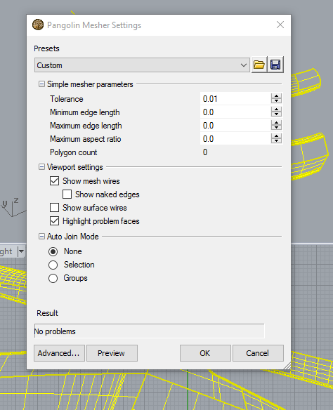
Command Buttons

You can check the rendering mesh result before committing it to the model by pressing the “Preview” button.
Pressing “OK” will add the mesh(es) to the model. Cancel will stop the process without making any changes to the model.
The “Advanced…” button switches to the advanced UI. See “Advanced…” below.
Other Settings
Presets
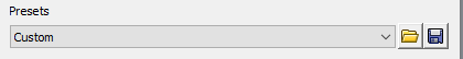
Pangolin can switch between a number of preset settings. The presets are stored in XML files in a special folder in your computer’s user account. You can open this folder by clicking the “Open” icon to the right of the combo box.
- You can switch to any of the installed presets by choosing the name from the combo box.
- To install new presets, or delete existing presets just add or remove xml files from the folder.
- The current settings can be saved to the presets folder by pressing the “Save” button.
- You can control the settings that appear the first time you run PangolinMesh in a session of Rhino by saving a file called “default.xml” in the preset folder.
Simple Meshing Parameters
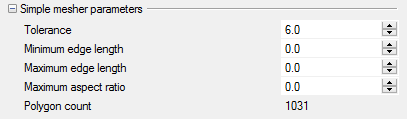
Each of the following values can be optionally ignored by setting them to 0.0.
Tolerance
Sets the maximum distance that the center of a mesh face will deviate from the input surface.
Minimum edge length
Removes small triangles during the initial subdivision phase by ensuring mesh edge lengths do not drop below the specified value.
Maximum edge length
Causes additional subdivision of a mesh face if edge lengths exceed the specified value.
Maximum aspect ratio
Causes additional subdivision of a mesh face if its aspect ratio exceeds the specified value. This can be used to remove long thin triangles, although please note that it only affects the initial subdivision, not the final tessellation.
Polygon count
Displays the number of mesh faces created if the current settings are used. Click the “Preview” button to generate the render mesh.
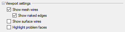
These settings determine how the mesh and polysurfaces are presented after the Preview button has been pressed.
Show mesh wires
If checked, the mesh wires of the preview render mesh will be displayed.
Show naked edges
If checked, naked edges on the preview rendering mesh will be highlighted. (Not yet implemented)
Show surface wires
If checked, the surface edges and iso-params of the input polysurfaces will be displayed.
Highlight problem faces
If checked, polysurfaces that reported a problem or a warning will be highlighted in red and yellow respectively.
Auto-join mode
The auto-join mode determines the way Pangolin creates rendering meshes from unjoined input polysurfaces. If two polysurfaces are adjacent but un-joined, Rhino will not treat them as being joined and will create two meshes whose edge vertices may not align. This means that the two meshes cannot be joined into a watertight mesh after the meshing operation, and may show gaps between the parts when rendered.
Pangolin’s “auto-join” feature attempts to treat adjacent polysurfaces as a single joined object and will create the meshes with co-aligned vertices. It is possible to control which polysurfaces should be considered joined by using the PangolinGroups feature. The options for auto-joining are:
None
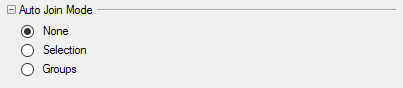
Each individual polysurface will result in an individual rendering mesh. No attempt will be made to align vertices between adjacent rendering meshes. (This works similarly to the Rhino mesh command)
Selection
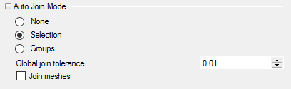
All of the polysurfaces in the current selection will be checked for adjacency with each other. If the distance between their edges is less than the “Global join tolerance”, they will be treated as joined and the rendering meshes will be created with aligned vertices.
In Selection mode, all groups defined in the PangolinGroups panel will be ignored when checking for input surface adjacency.
If the “Join Meshes” check box is checked, rendering meshes from adjacent input polysurfaces on the same layer will be joined into a single render mesh.
Groups
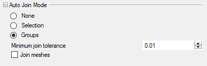
Polysurfaces will be tested for adjacency with other polysurfaces in the same group. The group of a polysurface is determined by the group its layer is placed in on the PangolinGroups panel.
Grouped polysurfaces are considered adjacent if they are closer than the minimum join tolerance - or they are closer than the minimum join tolerance specified for that group in the PangolinGroups panel, whichever is the larger value.
Adjacent grouped polysurfaces will have their meshes generated with aligned vertices so that they can be joined into a watertight mesh.
If the “Join Meshes” check box is checked, meshes from adjacent input polysurfaces on the same layer will be joined into a single rendering mesh which will eliminate any gaps in the tessellation between surfaces.
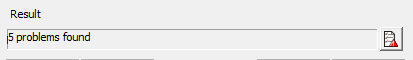
Result
The result field shows reported problems and warnings from the preview meshing process. The “Preview” button must be pressed to show these results.
Clicking the “Tag and Close” button on the right of the field closes the Pangolin Mesher Settings dialog and adds a text dot object at the location of each problem and warning. More information about the reported problem or warning can be found in the Pangolin Object Properties page for each text dot.
Clicking the “Tag and Close” button on the right of the field closes the Pangolin Mesher Settings dialog and adds a text dot object at the location of each problem and warning. More information about the reported problem or warning can be found in the Pangolin Object Properties page for each text dot.
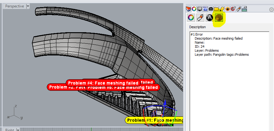
You can zoom into the object causing the problem report by pressing the “Zoom” button at the bottom of the object properties page when the text dot is selected. You can alternatively run the PangolinZoomSelected command to achieve the same result.
Advanced
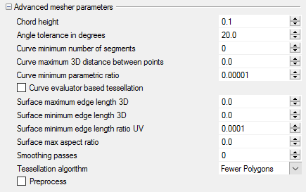
Clicking the “Advanced…” button at the bottom of the dialog switches the “Simple meshing parameters” to the “Advanced meshing parameters” set of controls. You can return to the “Simple meshing parameters” by clicking on the “Simple…” button.
The advanced parameters are for expert usage only and are only exposed to allow users to test the internal POPLib meshing parameters directly. They are not documented here. Further information is available in the POPLib documentation.
PangolinMesh groups
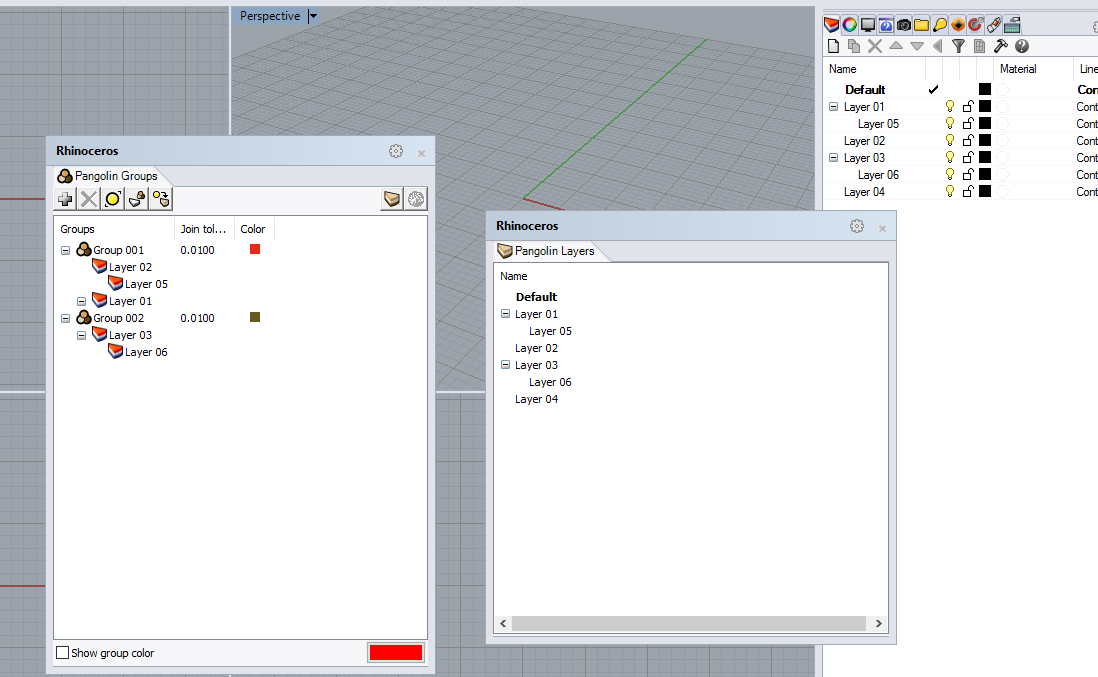
The Pangolin Groups panel is opened using the PangolinGroups command. In Rhino 5 it is used in combination with the Pangolin Layers panel (open using PangolinLayers command). In Rhino 6 the same functionality is available from the Rhino layers panel.
Pangolin groups determine how objects are associated with each other during the process of “auto-joining” when the meshing auto-join mode is set to Groups.
Objects are always grouped using their Rhino layer. Pangolin groups are a list of layers. A Pangolin group can contain any layer - including the sublayer of a layer that is in a different group. The Pangolin Groups panel shows the hierarchical relationship between layers in that group, but it is still possible to place sub-layers into other groups.
Managing Groups

Adding a group
Pangolin Groups are created by clicking the “+” button in the Pangolin Groups panel. Once created, layers are assigned to groups by dragging a layer from the Pangolin Layers panel (Rhino layers panel in Rhino 6) to a group in the Pangolin Groups panel. Dragging a parent layer will also add its sub-layers.
Deleting a group
Groups may be deleted using the Delete Group button on the panel toolbar or right clicking on the group.
Select objects not in a group
Clicking this button selects all of the objects in the current model that have not been assigned to a group. In other words, all objects that are on a layer that has not been added to one of the groups.
Select layers not in a group
Selects all of the layers in the Pangolin Layers panel (or Rhino 6 layers panel) that have not been assigned to a group.
Select layers from objects selection
Selects the layers in the Pangolin Layers panel (or Rhino 6 layers panel) that the selected objects is on.
Open the layers panel
Opens the PangolinLayers panel (or Rhino 6 layers panel).
Run the mesher command
Opens the mesher dialog - runs PangolinMesh
Group color
Groups are assigned a color at random when they are created. This color is used to identify objects within the group when the “Show group color” checkbox is checked (at the bottom of the panel). Those objects not in a group are shown in the color selected by the color button at the bottom right of the panel.
Per-group join tolerance
Join tolerance can be specified per-group. See Groups for more information.
